KYN28A-12 Installation Instructions
1 Overview
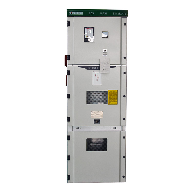
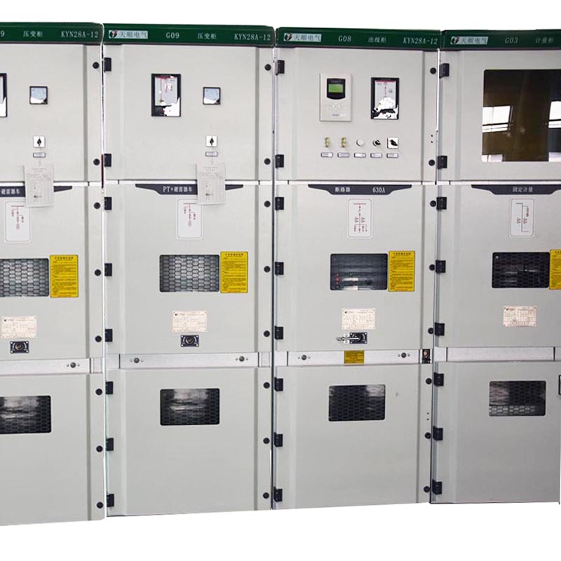
KYN28A-12 indoor metal armored central switchgear (hereinafter referred to as switchgear) is the latest generation of three-phase AC 50Hz, 3~12KV single busbar segmentation system developed by Tianshun Electric Co., Ltd. It is mainly used in power distribution systems of power plants, substations, industrial and mining enterprises, residential quarters, high-rise buildings, schools, etc., as a means of receiving and distributing electrical energy, and has functions of controlling, protecting and monitoring circuits. This type of relay chamber panel can be installed with various types of microcomputer-type integrated relay protection devices, which can realize intelligent control of the system. It has remote control, telemetry, remote signaling and remote adjustment functions. It is controlled by CAN bus with communication interface. Field network. It also has the function of preventing accidental operation of the circuit breaker, preventing the push and pull of the load, preventing the grounding switch from being charged, preventing the grounding switch from being powered at the grounding position, and preventing the accidental charging interval, that is, the "five-proof" function. The switchgear can be equipped with VS1, VD4, VB2 and other series of vacuum circuit breakers.
2. The external dimensions and weight of the equipment are shown in Table 1 and Figure 1.
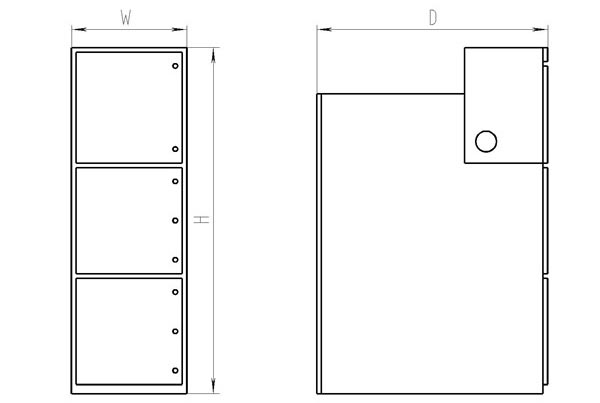
Table 1
|
Height H (mm) |
2300(2200) |
|
Width W (mm) |
Branch busbar rated current up to 1250A, thermal stable current 40kA |
800 |
|
Branch busbar rated current 1600A and above |
1000 |
|
Depth D (mm) |
Cable entry and exit line |
1500 |
|
Overhead access line |
1660 |
|
Weight (kg) |
700~1200 |
|
Serial number |
project |
单位 |
data |
|
1 |
Rated voltage |
kV |
12 |
|
2 |
Rated insulation level |
1min power frequency withstand voltage |
kV |
42 |
|
Lightning impulse withstand voltage |
kV |
75 |
|
3 |
Rated frequency |
Hz |
50 |
|
4 |
Main busbar rated current |
A |
630,1250,1600,2000,2500,3150,4000 |
|
5 |
Branch busbar rated current |
A |
630,1250,1600,2000,2500,3150,4000 |
|
6 |
4s thermal stable current (effective value) |
kA |
16,20,25,31.5,40,50 |
|
7 |
Rated dynamic stability current (peak)* |
kA |
40,50,63,80,100,125 |
|
8 |
Protection level |
|
The enclosure is IP4X; the compartment and circuit breaker door are IP2X when opened |
Note: * The short circuit capacity of the current transformer should be considered separately.
Technical parameters of vacuum circuit breaker
|
Serial number |
name |
unit |
Parameter |
|
1 |
Rated voltage |
kV |
12 |
|
2 |
Rated frequency |
Hz |
50 |
|
3 |
Rated current |
A |
630
1250 |
630
1250 |
1250
1600
2000
2500
3150 |
1250
1600
2000
2500
3150 |
|
4 |
Rated short-circuit breaking current |
kA |
20 |
25 |
31.5 |
40 |
|
5 |
Rated short-circuit withstand current |
20 |
25 |
31.5 |
40 |
|
6 |
Rated short circuit duration |
S |
4 |
|
7 |
Rated peak withstand current |
kA |
50 |
63 |
80 |
100 |
|
8 |
Rated short circuit closing current |
50 |
63 |
80 |
100 |
|
9 |
Rated insulation level |
1min power frequency withstand voltage |
kV |
42 |
|
Lightning impulse withstand voltage |
75 |
|
10 |
Secondary circuit power frequency withstand voltage (1min) |
V |
2000 |
|
11 |
Rated operation sequence |
|
O-0.3s-CO-180s-CO(小于40kA)
O-180s-CO-180s-CO(40kA) |
|
12 |
Mechanical life |
次 |
M2级(10000) |
|
13 |
Operating mechanism |
Energy storage motor |
Rated voltage |
V |
AC110/220DC110/220 |
|
Energy storage time |
s |
≤15 |
|
Closing trip coil |
Rated voltage |
V |
AC110/220DC110/220 |
|
14 |
Contact opening distance |
mm |
11±1 |
|
15 |
Contact stroke |
3.5±0.5 |
|
16 |
Three-phase tripping synchronization |
ms |
≤2 |
|
17 |
Contact closing bounce time |
≤2 |
|
18 |
Contact closing contact pressure |
N |
2000±200 (20kA)
2400±200 (25kA)
3100±200 (31.5kA)
4750±250 (40kA) |
|
19 |
Average opening speed |
m/s |
0.9~1.2 |
|
20 |
Average closing speed |
0.5~0.8 |
|
21 |
Opening time (at rated operating voltage) |
ms |
20~55 |
|
22 |
Closing time (at rated operating voltage) |
35~70 |
|
23 |
Conductive loop resistance |
μΩ |
≤65(630A)
≤55(1250A)
≤35(1600A~2000A)
≤25(2500A及以上) |
Note: 1. The average opening speed refers to the average speed of the circuit breaker contact just after 6mm;
2. The average closing speed refers to the average speed of the full opening distance of the circuit breaker.
4. Structure
The equipment is designed according to the armored metal-enclosed switchgear in GB3906. The whole body is composed of two parts: the cabinet and the middle-mounted removable parts (ie, the handcart), as shown in Figure 2. The cabinet is divided into four separate compartments, the enclosure is IP4X, and the protection level is IP2X when the compartments and circuit breaker compartments are open. With overhead access lines, cable access lines and other functional solutions, the switch cabinets of each solution can be arranged to form a power distribution device capable of designing functions according to the application. The unit can be installed, commissioned and maintained from the front, so it can be stacked back-to-back or wall-mounted, increasing equipment safety, flexiblity and floor space
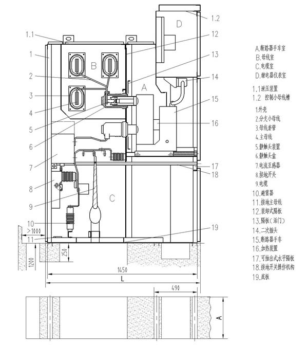
Figure 2 Grounding diagram of switchgear
Table 4
|
Cabinet width A (mm) |
use |
柜体深度L(mm) |
|
800 |
Cable entry and exit line |
1500 |
|
Overhead access line |
1660 |
|
1000 |
Cable entry and exit line |
1500 |
|
Overhead access line |
1660 |
|