

 English
 中文简体
中文简体 Español
 عربى
عربى
High Voltage Line Layout Guide: Safe, Efficient Distribution Design
Admin 2026-08-21Content
- 1 The Direct Answer: How High Voltage Lines Should Be Arranged
- 2 Key Layout Configurations for High Voltage Lines
- 3 Insulation Coordination and Safety Margins
- 4 Integrating Layout with High-Voltage Distribution Equipment
- 5 Environmental and Terrain Considerations
- 6 Common Layout Mistakes and Best Practices
- 7 Maintenance Access and Corridor Planning
- 8 Summary: What a Well-Arranged Line Delivers
The Direct Answer: How High Voltage Lines Should Be Arranged
A well-planned high voltage line layout keeps conductors at safe vertical and horizontal distances from each other, from structures, and from the ground, while matching the mechanical and electrical demands of the High-Voltage Distribution Equipment connected at each end. In practical terms, this means choosing the correct conductor configuration (horizontal, vertical, or triangular), maintaining minimum air clearances based on voltage class, and coordinating span length with tower or pole strength. Utilities that follow these three fundamentals reduce flashover risk, lower maintenance costs, and extend equipment service life by a significant margin.
Poor arrangement is one of the leading causes of unplanned outages in overhead networks. A conductor spaced too closely to a neighboring phase, or a line routed without accounting for wind sway, can trigger arcing events that damage switchgear, transformers, and other connected distribution assets. This article breaks down the arrangement principles, clearance figures, and integration practices that keep a high voltage corridor performing as designed.
Key Layout Configurations for High Voltage Lines
Three conductor arrangements dominate overhead high voltage design, and each one is chosen based on right-of-way width, terrain, and the type of High-Voltage Distribution Equipment the line will feed. The table below compares the three most common configurations used in medium to high voltage corridors.
| Configuration | Typical Use Case | Advantage | Limitation |
|---|---|---|---|
| Horizontal | Wide right-of-way, rural feeders | Simplifies insulator maintenance | Requires wider corridor |
| Vertical | Narrow urban corridors | Minimizes lateral footprint | Taller poles or towers needed |
| Triangular (Delta) | Mixed terrain, transmission spans | Balances height and width | More complex tower design |
Selecting the wrong configuration for the site conditions is a common design error. A vertical arrangement forced onto a wide, unobstructed rural corridor wastes tower height and increases wind loading, while a horizontal arrangement squeezed into an urban strip often violates minimum setback rules.
Minimum Clearance and Spacing Requirements
Clearance is the single most important variable in high voltage line arrangement. Spacing must account for conductor sag under load, wind-induced swing, and ice accumulation in colder climates. General industry practice for phase-to-phase and phase-to-ground clearance scales with voltage class:
- Below 33 kV: phase-to-phase spacing typically starts around 0.5 to 1 meter, adjusted for span length
- 33 kV to 132 kV: spacing generally increases to 1.5 to 3 meters depending on tower type
- Above 132 kV: spacing can exceed 4 meters, with additional margin for switching surge overvoltages
- Ground clearance at midspan must account for maximum conductor temperature and worst-case sag, not the clearance measured at installation
These figures are general planning references and always require verification against the applicable local grid code and the manufacturer's rated clearance for the specific High-Voltage Distribution Equipment being installed on the line.
Insulation Coordination and Safety Margins
Arrangement and insulation coordination are inseparable. Even a correctly spaced conductor can flash over if the insulator string, arrester rating, or creepage distance is mismatched with the site's pollution level and altitude. Insulation coordination ensures that every component along the line, from the conductor to the connected switchgear, shares a consistent withstand voltage margin.
Practical Coordination Checklist
- Match insulator creepage distance to the site pollution class (light, medium, heavy, or very heavy)
- Verify surge arrester rating against the maximum expected switching and lightning overvoltage
- Adjust clearance upward at higher altitudes, since reduced air density lowers dielectric strength
- Confirm that all connected distribution equipment shares a compatible basic insulation level (BIL)
Integrating Layout with High-Voltage Distribution Equipment
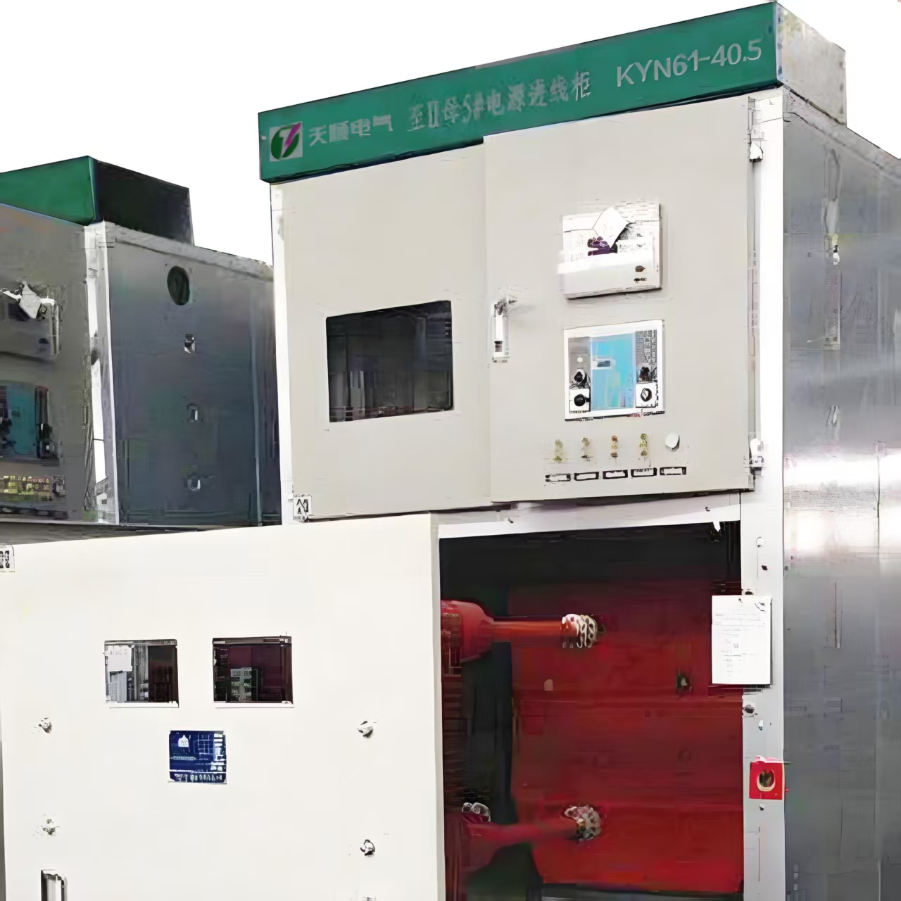
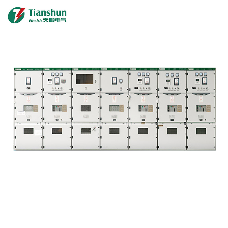
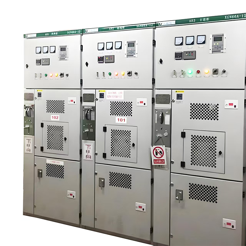
Line arrangement does not end at the tower or pole. The layout must feed cleanly into the switching stations, transformers, and metering enclosures that make up the broader High-Voltage Distribution Equipment network. Cable entry angles, busbar orientation inside the switchgear, and the physical approach of the overhead line all affect how easily the equipment can be maintained and how much stress is placed on terminations.
A layout that brings conductors into a substation at a sharp angle increases mechanical stress on bushings and terminal connectors, shortening their service life. A gentler approach angle, combined with adequate slack in the drop conductors, reduces vibration fatigue and simplifies future retrofits. Design teams that plan the line route and the distribution equipment location together, rather than treating them as separate projects, consistently report fewer post-commissioning corrections.
Environmental and Terrain Considerations
Terrain shapes almost every arrangement decision. Sloped ground changes effective clearance at each support point, so designers often specify taller structures or shorter spans on hillsides to preserve the required ground clearance under sag conditions. Coastal or high-humidity regions typically call for wider phase spacing and higher-grade insulators to offset accelerated pollution buildup on insulator surfaces.
Wind zones deserve particular attention. In areas with frequent high wind events, galloping conductors can momentarily close the gap between phases. Adding vertical offset between conductors, or installing spacer dampers, is a common and cost-effective mitigation that preserves the intended arrangement without redesigning the entire corridor.
Common Layout Mistakes and Best Practices
Field audits of underperforming corridors tend to surface the same recurring issues. Recognizing them early during the design phase avoids costly retrofits after commissioning.
- Underestimating conductor sag at maximum operating temperature, resulting in reduced ground clearance during peak load periods
- Placing structures at uneven spans without adjusting tension, which creates uneven sag and localized clearance violations
- Ignoring vegetation growth rates when setting the initial right-of-way width
- Failing to coordinate the line route with the maintenance access path required for the connected distribution equipment
Best practice is to treat arrangement as a full lifecycle decision, not a one-time calculation. Reviewing clearance and spacing at the design stage, again during construction sign-off, and periodically through aerial or ground inspection keeps the corridor within its original safety envelope for decades.
Maintenance Access and Corridor Planning
A technically correct arrangement still fails in practice if crews cannot safely access it. Corridor planning should reserve space for bucket trucks, cable pulling equipment, and emergency repair vehicles alongside the electrical clearance requirements. Access roads parallel to the line reduce outage duration significantly, since crews reach the fault point without needing to cut through vegetation or cross private property.
Regular thermal imaging and visual inspection of both the line and the connected High-Voltage Distribution Equipment should be built into the maintenance schedule from day one. Early detection of a loose connector or a degraded insulator at the equipment interface is far less costly than responding to a fault after it has already interrupted service.
Summary: What a Well-Arranged Line Delivers
When conductor configuration, clearance, insulation coordination, and terrain factors are addressed together, the result is a corridor that resists flashover, tolerates environmental stress, and connects cleanly to substation and distribution assets. Utilities and engineering teams that apply these principles consistently see fewer weather-related outages and lower long-term maintenance spend, making disciplined layout planning one of the highest-value steps in any high voltage project.
For exclusive deals and latest offers, sign up by entering your email address below.

-
Please feel free to contact us if needed!
Contact Us -
Quick Links
Home About Us Products Applications News Contact -
Contact Us
nbtsdq@163.com +86-15757467313 +86-574-65800646 No. 1, Jiuzhou Road, Xiangshan County, Ningbo City, Zhejiang Province, China -
Get Touch
