

 English
 中文简体
中文简体 Español
 عربى
عربى
High-Voltage Switchgear Guide: Powering Safe Transmission High Voltage Networks
Admin 2026-08-07Content
- 1 What High-Voltage Switchgear Does for Transmission High Voltage Systems
- 2 How High-Voltage Switchgear Protects and Controls the Grid
- 3 Key Types of High-Voltage Switchgear Used in Transmission Applications
- 4 Critical Technical Specifications to Evaluate Before Selecting High-Voltage Switchgear
- 5 Installation and Maintenance Best Practices for Transmission High Voltage Switchgear
- 6 Common Failure Modes and How Design Choices Prevent Them
- 7 Choosing a Reliable High-Voltage Switchgear Solution for Transmission Projects
What High-Voltage Switchgear Does for Transmission High Voltage Systems
The direct answer is this: high-voltage switchgear is the equipment responsible for switching, isolating, and protecting transmission high voltage circuits from overload, short-circuit faults, and unsafe operating conditions. Without it, transmission high voltage networks would have no reliable way to interrupt fault currents, which can exceed tens of thousands of amperes in a matter of milliseconds. Every substation, generation plant, and long-distance transmission corridor depends on high-voltage switchgear as the primary control layer between power sources and the grid.
In practical terms, high-voltage switchgear combines circuit breakers, disconnectors, earthing switches, current transformers, and protection relays into a single coordinated system. This system allows operators to safely energize or de-energize sections of a transmission high voltage line, isolate equipment for maintenance, and clear faults before they cascade into wider blackouts. Utilities and industrial power users alike rely on this equipment because a single uncontrolled fault on a transmission high voltage line can damage transformers, generators, and connected loads within seconds.
How High-Voltage Switchgear Protects and Controls the Grid
High-voltage switchgear performs three interconnected functions within any transmission high voltage system: switching, isolation, and protection. Understanding how each function operates explains why switchgear reliability is treated as a non-negotiable design requirement by grid operators.
Switching Function
Circuit breakers inside high-voltage switchgear open and close under load, redirecting power flow across transmission high voltage lines without interrupting service to unaffected sections of the network.
Isolation Function
Disconnectors and earthing switches within high-voltage switchgear create a visible, physical break in the circuit, allowing maintenance crews to work safely on de-energized transmission high voltage equipment.
Protection Function
Protection relays paired with high-voltage switchgear detect abnormal current or voltage patterns and trigger breaker tripping within 2 to 5 cycles, typically under 100 milliseconds, to limit fault energy and prevent equipment destruction.
Key Types of High-Voltage Switchgear Used in Transmission Applications
Not all high-voltage switchgear is built the same way. The choice between designs depends on voltage class, available footprint, environmental exposure, and maintenance strategy. The table below summarizes the most common configurations found in transmission high voltage installations.
| Switchgear Type | Typical Voltage Range | Insulation Medium | Best Suited For |
|---|---|---|---|
| Air-Insulated Switchgear (AIS) | 72.5 kV – 550 kV | Open air | Large open-air substations with abundant space |
| Gas-Insulated Switchgear (GIS) | 72.5 kV – 1100 kV | SF6 or eco-friendly gas mixtures | Compact urban substations, coastal or high-pollution sites |
| Hybrid Switchgear | 72.5 kV – 245 kV | Mixed gas and air modules | Retrofit or expansion projects with limited space |
For most new transmission high voltage projects above 245 kV, gas-insulated switchgear has become the preferred solution because it reduces substation footprint by up to 70 percent compared with air-insulated designs, while offering superior protection against contamination and moisture ingress.
Critical Technical Specifications to Evaluate Before Selecting High-Voltage Switchgear
Selecting high-voltage switchgear for a transmission high voltage project is not a one-size-fits-all decision. Engineers should verify the following parameters against project requirements before finalizing equipment specifications.
- Rated voltage and insulation level, matched to the nominal system voltage plus an appropriate safety margin
- Rated short-circuit breaking current, generally specified between 31.5 kA and 63 kA for major transmission high voltage substations
- Rated normal current, which determines continuous thermal capacity under full load
- Mechanical and electrical endurance class, indicating how many operating cycles the switchgear can perform before service
- Ambient temperature range and altitude correction factors for the installation site
- Seismic withstand rating, particularly important for substations located in active fault zones
Overlooking any single specification can lead to premature failure or costly retrofitting. A common industry benchmark requires high-voltage switchgear to achieve a design life of at least 30 years under normal operating conditions, so specification accuracy at the procurement stage has long-term financial consequences.
Installation and Maintenance Best Practices for Transmission High Voltage Switchgear
Proper installation and a disciplined maintenance schedule extend the operational life of high-voltage switchgear and reduce unplanned outages across transmission high voltage networks.
Installation Guidelines
Site preparation must account for grounding grid resistance, foundation load capacity, and clearance distances defined by the applicable voltage class. Gas-insulated high-voltage switchgear additionally requires strict gas-handling procedures during commissioning to avoid moisture contamination inside sealed compartments.
Maintenance Guidelines
Routine inspection intervals for high-voltage switchgear typically follow a 12-month visual inspection cycle and a 3 to 6 year detailed maintenance cycle, depending on operating conditions and manufacturer recommendations. Key checks include contact resistance measurement, SF6 gas density verification, mechanism lubrication, and protection relay calibration testing.
- Monitor gas pressure and density trends to detect leaks before they affect dielectric strength
- Perform contact resistance testing to identify wear before it causes overheating
- Verify trip and close timing to confirm mechanical operation remains within tolerance
- Inspect insulation surfaces for tracking, contamination, or partial discharge activity
Common Failure Modes and How Design Choices Prevent Them
Understanding why high-voltage switchgear fails helps engineers select equipment and maintenance strategies that minimize risk on transmission high voltage networks.
| Failure Cause | Effect on Transmission System | Preventive Measure |
|---|---|---|
| Contact overheating | Localized insulation degradation, potential fire risk | Silver-plated contacts, regular resistance testing |
| SF6 gas leakage | Reduced dielectric and interrupting capability | Sealed pressure system monitoring, leak detection sensors |
| Mechanism sticking | Delayed or failed breaker tripping during a fault | Scheduled lubrication, spring-charge motor inspection |
| Insulation contamination | Flashover risk, unplanned outage | Enclosed gas-insulated design, periodic surface cleaning |
Statistics gathered across the utility industry consistently show that the majority of switchgear failures stem from mechanical wear rather than electrical insulation breakdown, which reinforces why mechanical maintenance schedules deserve equal attention to electrical testing programs.
Choosing a Reliable High-Voltage Switchgear Solution for Transmission Projects
When evaluating a supplier of high-voltage switchgear for a transmission high voltage project, engineers and procurement teams should look beyond price and confirm manufacturing quality, type-test certification, and after-sales support capability. Equipment that has passed internationally recognized type tests for short-circuit breaking, temperature rise, and mechanical endurance offers a much lower long-term risk profile than uncertified alternatives.
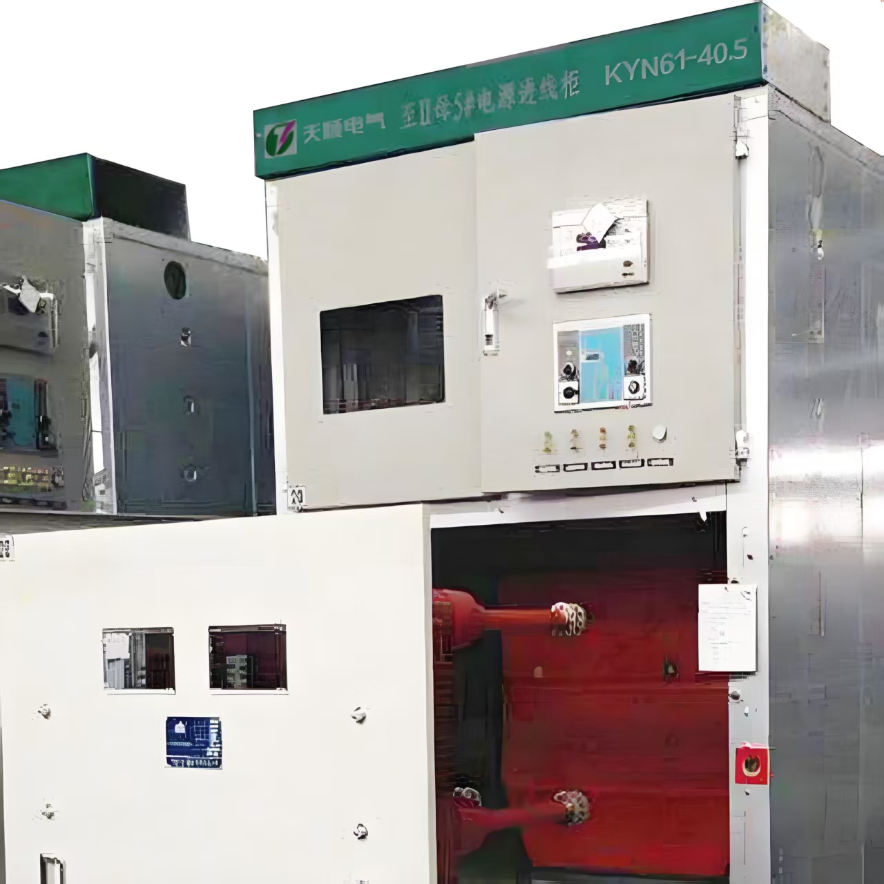
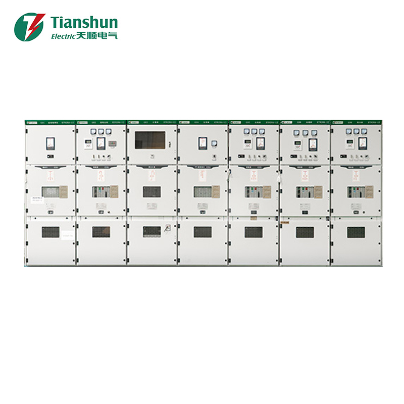
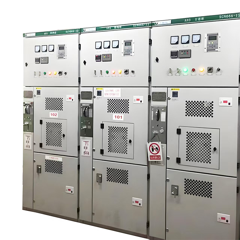
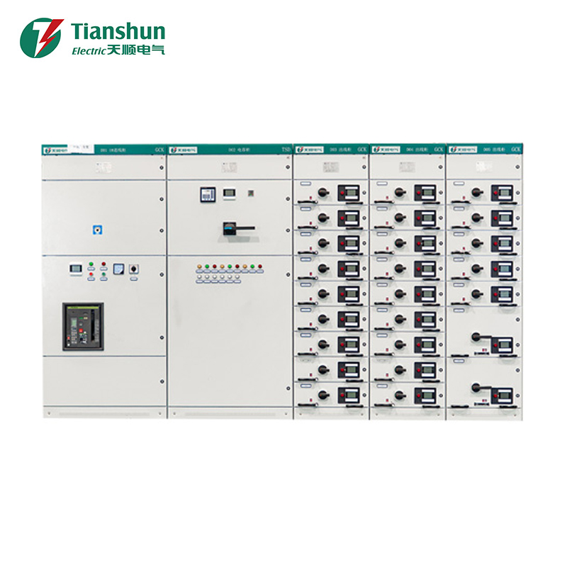
Our high-voltage distribution equipment lineup covers air-insulated, gas-insulated, and hybrid switchgear configurations engineered to meet the demanding operating conditions of transmission high voltage networks, from coastal substations to high-altitude installations. Each unit is designed with serviceability in mind, allowing maintenance teams to perform inspections and component replacement without extended downtime.
Project teams planning a new substation or retrofit can review detailed specifications, voltage classes, and configuration options on our high-voltage distribution equipment product page, where technical documentation supports side-by-side comparison against project requirements.
In summary, high-voltage switchgear remains the single most important protective layer within any transmission high voltage network, and its selection deserves the same engineering rigor applied to transformers, transmission towers, and conductor design. A well-specified, properly maintained switchgear system directly translates into fewer outages, lower lifecycle costs, and a safer operating environment for both personnel and equipment.
For exclusive deals and latest offers, sign up by entering your email address below.

-
Please feel free to contact us if needed!
Contact Us -
Quick Links
Home About Us Products Applications News Contact -
Contact Us
nbtsdq@163.com +86-15757467313 +86-574-65800646 No. 1, Jiuzhou Road, Xiangshan County, Ningbo City, Zhejiang Province, China -
Get Touch
