

 English
 中文简体
 Español
 عربى

High Tension Transmission Lines: Voltage Classes, Hardware, and Sourcing
Admin 2026-11-06Content
- 1 What High Tension Covers
- 2 Why the Voltage Rises Before the Current Does
- 3 The Hardware That Makes Up the Line
- 4 Overhead Against Underground
- 5 Where the Line Meets the Station
- 6 Clearance, Right of Way and the Safety Case
- 7 What to Put in the Specification
- 8 The Line Sets the Voltage, the Station Sets the Reliability
A 132 kV circuit running 80 km between two substations, built with a two conductor bundle of 400 mm2 ACSR per phase, will carry about 150 MVA and lose under three percent of that energy in the conductors. None of that performance is decided on the tower alone. Conductor size, insulator creepage, tower loading and the switchgear at each end are chosen together, and one weak choice resets the rating of the whole line.
What follows is a practical view of high tension transmission lines: what the voltage bands actually mean, why the voltage is raised before the current is, how the hardware is selected, where overhead and underground routes diverge, and what belongs in the specification before an order is placed.
What High Tension Covers
High tension is a term with two lives. In South Asian utility practice it usually describes 11 kV and 33 kV overhead feeders that step down to 415 V low tension supply. In transmission planning the same phrase is used for lines from 66 kV upward, where the job is bulk transfer rather than local delivery. Clearances, insulator counts and terminating equipment change with the band.
| Band | Typical levels | Main duty | Hardware character |
|---|---|---|---|
| High tension distribution | 11 kV, 33 kV | Feeds towns, industrial parks and transformer kiosks | Pin or post insulators, single conductor per phase, 20 to 30 m spans |
| Subtransmission | 66 kV, 110 kV, 132 kV | Links bulk supply points over 20 to 80 km | Suspension strings of 9 to 11 discs, single or twin bundle, corridor 20 to 30 m |
| Transmission | 220 kV, 330 kV, 400 kV, 500 kV | Long distance bulk transfer between regions | Two to three sub conductors, 20 to 25 disc strings, corridor 30 to 50 m |
| Extra and ultra high | 765 kV AC, 800 kV DC | Very long haul from large generation centres | Four to eight sub conductors, tall lattice towers, corridor 50 m and above |
The practical consequence is that a 33 kV feeder and a 400 kV line share a principle and almost no hardware. A specification written for one band cannot be reused for the other without a full review of insulation, conductor and protection.
Why the Voltage Rises Before the Current Does
Raising voltage is the cheapest way to push more power through a fixed conductor, and the saving is not marginal. For a given power, current falls in proportion to voltage, and resistive loss falls with the square of that current.
Compare 400 MVA at 220 kV with the same 400 MVA at 400 kV over 100 km of line at 0.06 ohm per km, so 6 ohm per phase. At 220 kV the current is about 1050 A and the three phase loss is roughly 19.8 MW. At 400 kV the current is about 577 A and the loss drops to roughly 6.0 MW. Same power, one third of the heat, and a conductor that runs cooler and sags less on a hot afternoon.
There is a ceiling. Each line has a surge impedance loading, roughly 130 MW at 220 kV and 500 MW at 400 kV with normal phase spacing, above which voltage control rather than thermal rating becomes the binding limit. That is why long routes add shunt reactors, series compensation or switched capacitor banks, and why the highest voltages only pay back on genuinely large transfers.
The Hardware That Makes Up the Line
Conductors and bundles
ACSR remains the default for its strength to weight ratio, while AAAC is chosen where corrosion matters more than tensile strength. Above 220 kV the phase is split into two, three or four sub conductors spaced 300 to 450 mm apart. The bundle raises the effective diameter, cuts corona loss and audible noise, and lowers inductive reactance by roughly a quarter, which directly increases transfer capability.
Insulators
Cap and pin strings of toughened glass or porcelain, or composite silicone insulators on shorter spans. Creepage follows the pollution map: about 25 mm per kV for light pollution and 31 mm per kV or more for coastal and industrial sites with salt and cement dust. A 132 kV string typically uses 9 to 11 discs, a 400 kV string 22 to 25.
Towers and foundations
Lattice steel towers dominate because they are stiff, ship in sections and cost less per metre of height. Tubular monopoles win where the corridor is tight. Designs are checked for broken wire loads, combined ice and wind cases, and differential settlement, and on rural routes the foundations are often the longest lead item.
Shield wires and earthing
One or two earth wires sit above the phases, usually with an optical fibre core for communications. Tower footing resistance decides lightning performance more than anything else: below 10 ohm is a common target, and a tower that misses it will back flashover even under a perfect insulator string.
Overhead Against Underground
Almost every high tension transmission line is overhead, and the reason is arithmetic rather than habit. For the same capacity, an underground cable route costs roughly five to ten times the overhead option at 132 kV, and considerably more at 400 kV.
Where overhead wins
- Lowest cost per km and the fastest route to energisation.
- Faults are visible and repairs take hours to days, not weeks.
- Thermal capacity holds up in still air and uprating is possible by reconductoring.
- Corridors can often share land with roads, rail and agriculture.
Where cable is the right answer
- Dense urban entry points and short substation connections.
- Crossings of wide waterways and airport approach zones.
- Protected landscapes where consent for towers is impossible.
- Short lengths where charging current stays manageable.
The hidden cost of cable is reactive. A 400 kV cable generates far more charging current than an overhead line of the same length, so compensation and terminal equipment grow, and a fault takes days to locate and weeks to repair because the route must be excavated.
Where the Line Meets the Station
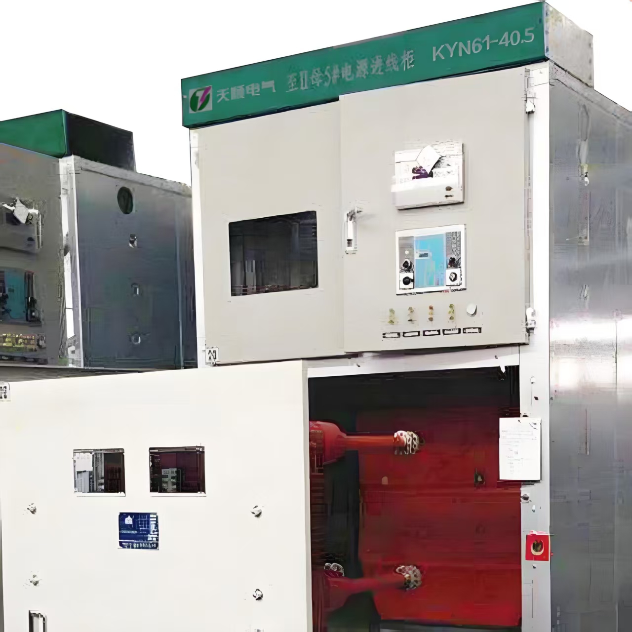
A transmission line ends at a busbar, and everything downstream protects and controls that interface: incoming isolators, circuit breakers, current and voltage transformers, surge arresters and the step down transformer. The switchgear must interrupt whatever fault level the network can deliver, commonly 25 or 31.5 kA at 12 kV and 40 kA at 40.5 kV, and it must do so after years of standing mostly idle.
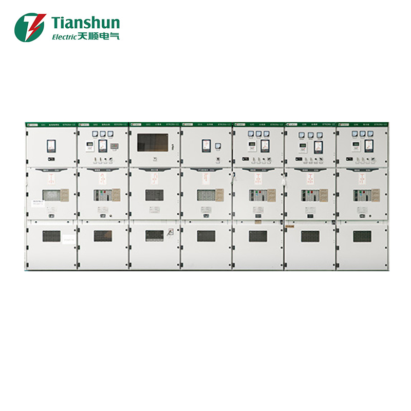
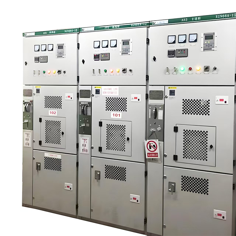
On the medium voltage side, metal clad switchgear is the equipment operators live with. A 12 kV cubicle with a withdrawable breaker lets a faulted feeder be swapped in minutes instead of being isolated for a day.
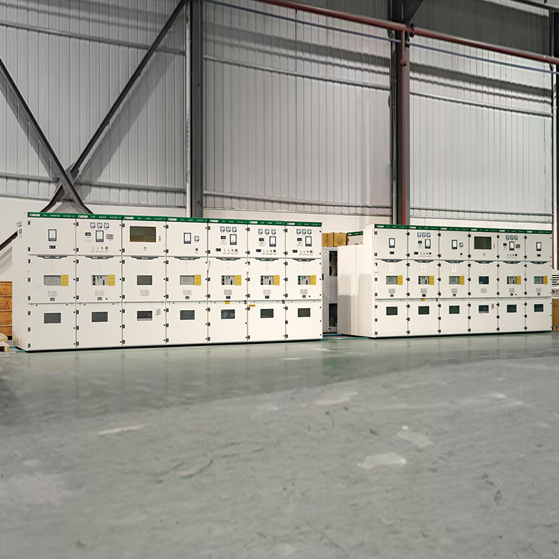 KYN28A-12 12 kV Indoor Metal-Clad Withdrawable SwitchgearA 12 kV indoor armored switchgear with withdrawable breaker compartments, mechanical interlocks, and ratings up to 4000 A for medium-voltage distribution.View Product →
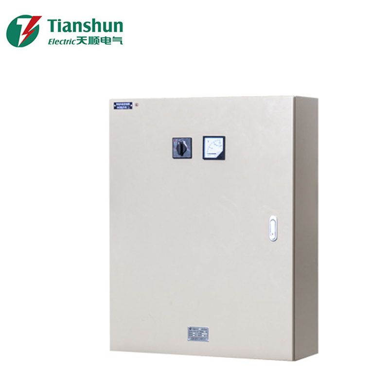
For routes that end in a distribution network rather than a large substation, a prefabricated substation packs the transformer, medium voltage switchgear, low voltage distribution and protection into one factory assembled enclosure. Site civil work shrinks, commissioning shortens, and interface tolerances sit with a single supplier.
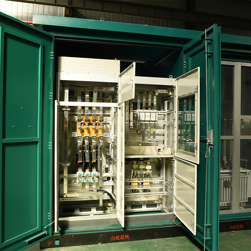 YB-12/0.4 Outdoor Prefabricated Box-Type SubstationFactory-assembled 12 kV/0.4 kV substation integrating HV switchgear, transformer, and LV distribution for faster outdoor deployment and reduced site work.View Product →
The transformer closes the chain. Dry type units are preferred inside buildings, tunnels and metro stations because they remove the oil and the fire load that comes with it, while oil immersed units stay cheaper per MVA outdoors.
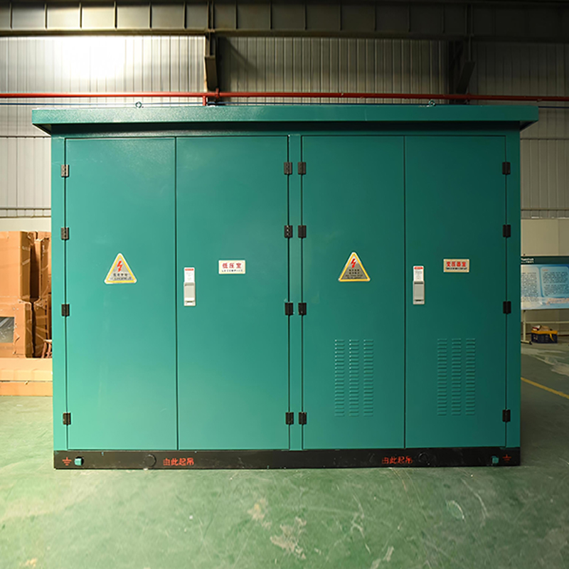 SCB13 and SCB14 Cast-Resin Dry-Type Transformers10 kV epoxy resin cast dry-type transformers from 630 to 2000 kVA, offering oil-free fire safety and simpler indoor installation for distribution projects.View Product →
Clearance, Right of Way and the Safety Case
Clearances are not rules of thumb. They come from switching surge levels, altitude correction and the maximum sag at the highest conductor temperature. Five checks cover most of the risk.
- Ground clearance is stated at the maximum sag for design temperature, not the stringing sag, plus the statutory clearance for the route class. Agricultural crossings usually need more than the minimum because machinery passes underneath.
- Phase to phase and phase to structure distances follow the basic insulation level of the line, with an altitude correction above 1000 m.
- Right of way runs 20 to 30 m for 132 kV and 30 to 50 m for 400 kV on typical lattice towers, wider where the route deviates.
- Electric and magnetic fields at the corridor edge are checked against local limits, and most 132 kV lines sit well below 5 kV per metre at the boundary.
- Vegetation and access are specified with the conductor to tree clearance and the maintenance track, because a line that cannot be reached cannot be repaired.
What to Put in the Specification
Most disputes on line and station equipment trace back to a missing ambient condition rather than a manufacturing defect. This is the minimum that should travel with the enquiry.
- System data: nominal and highest system voltage, fault level and duration, neutral earthing, frequency.
- Environment: ambient range, altitude, humidity, pollution class, seismic zone, solar exposure.
- Ratings: continuous current at site ambient, short time withstand, peak withstand, and the temperature rise limit at the terminals.
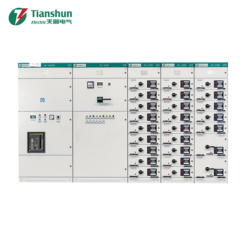
- Standards and evidence: IEC 62271 for switchgear, IEC 61439 for low voltage assemblies, IEC 60076 for transformers, with type test reports matching the design offered and routine test certificates for every unit.
- Interfaces: cable box type and size, busbar arrangement, protection and metering scheme, communication protocol, terminal numbering convention.
- Commercial: factory test witness rights, sea freight packing, site support days, spare parts list, and a warranty that starts at energisation rather than shipment.
The Line Sets the Voltage, the Station Sets the Reliability
A high tension transmission line is only as good as the equipment that terminates it. Creepage level, fault level and ambient temperature follow the same design inputs on the tower and in the switchgear room, so buying them as separate packages usually costs more than it saves.
If the project touches medium voltage distribution or a packaged substation, our engineers can review the single line diagram against the site conditions before the order is frozen. For background on how the distribution side is arranged, read what a high voltage distribution system includes, or send the drawing through the contact page.
For exclusive deals and latest offers, sign up by entering your email address below.

-
Please feel free to contact us if needed!
Contact Us -
Quick Links
Home About Us Products Applications News Contact -
Contact Us
nbtsdq@163.com +86-15757467313 +86-574-65800646 No. 1, Jiuzhou Road, Xiangshan County, Ningbo City, Zhejiang Province, China -
Get Touch
