

 English
 中文简体
 Español
 عربى
At a 132 kV site, one loose busbar connection can turn a routine switching operation into a multi-hour outage. A high-voltage electrical substation is the node where transmission lines, power transformers, protection systems, and distribution feeders meet. Reliability comes from coordination across those interfaces, not from one premium component.
The practical conclusion for owners and EPC teams is straightforward. Define voltage, fault level, duty cycle, and interface responsibilities before equipment selection. Then confirm how each item will be tested, earthed, maintained, and replaced.
What a High-Voltage Electrical Substation Does
A high-voltage electrical substation does more than change voltage. It switches circuits, isolates faults, regulates voltage, controls power flow, and provides the measurement point for protection and metering. Transmission substations connect generators, grid corridors, and bulk loads. Distribution substations step voltage down for industrial parks, commercial buildings, and public networks. The same facility may also host reactive compensation, earthing transformers, and auxiliary power.
- Switching and isolation for lines, transformers, and busbars
- Voltage transformation between transmission and distribution levels
- Fault detection, protection tripping, and post-fault recording
- Metering, control, and communication with grid operators
- Earthing, auxiliary supply, and safe maintenance access
For a closer look at how high-voltage distribution equipment fits into the wider network, see this overview of high-voltage distribution systems.
Core Equipment and Procurement Risk
The main transformer sets voltage ratio, impedance, losses, and noise. Switchgear interrupts fault current and provides visible isolation. Gas-insulated switchgear saves space in constrained sites, while air-insulated gear is easier to inspect. Current and voltage transformers feed protection relays, and the DC system keeps trip circuits alive during an outage. Every interface is a procurement risk because a mismatch in ratings, CT class, or communication protocol can delay energisation.
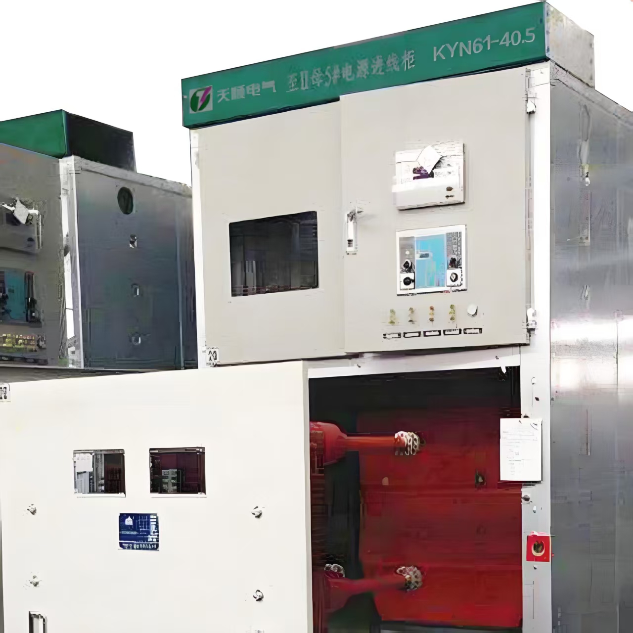
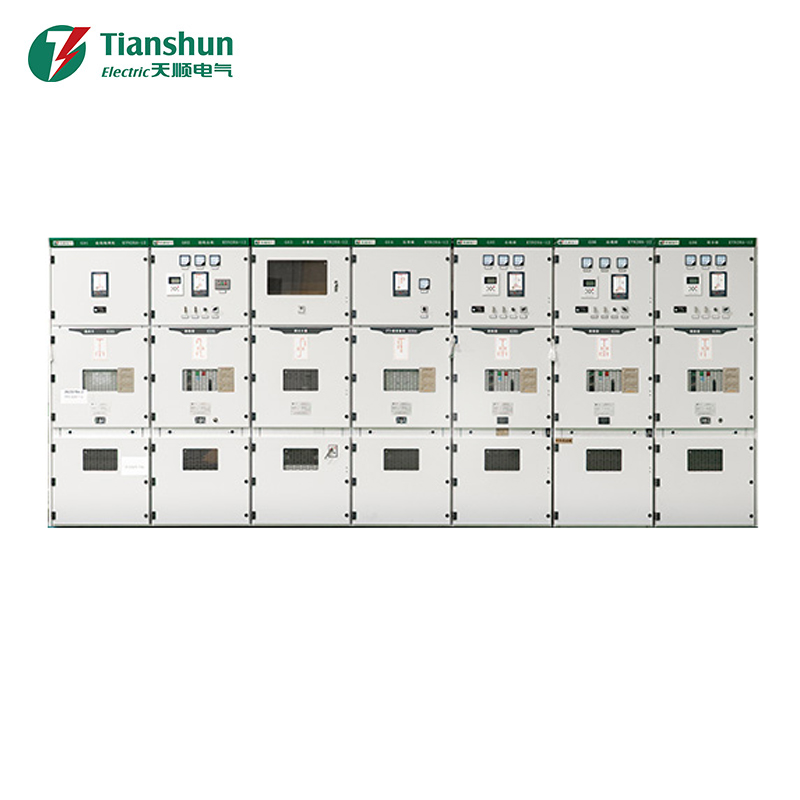
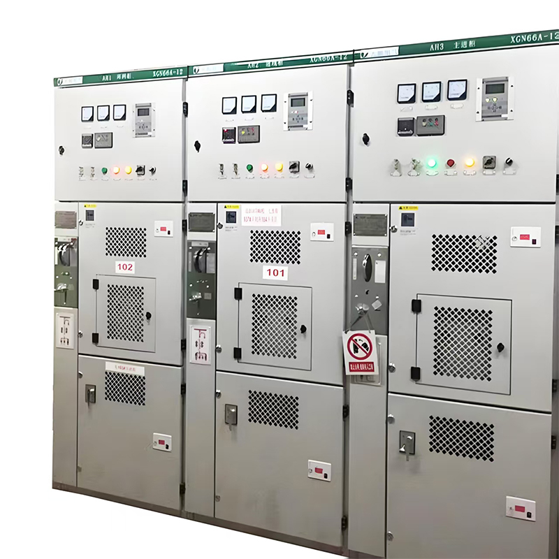
For indoor 12 kV distribution, metal-clad withdrawable switchgear is common. The KYN28A-12 family is one example of that format, with the breaker moving on a truck for service access.
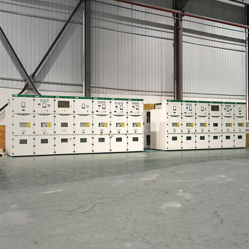 KYN28A-12 Indoor 12 kV Metal-Clad SwitchgearReview short-circuit rating, arc containment, cable termination space, and interlocks for indoor 12 kV distribution with withdrawable breaker service access.View Product →
Check short-circuit rating, arc containment, cable termination space, and interlocks against the single-line diagram. A low first price can become an expensive change order when the cable box or relay panel does not match the site interface.
Voltage Class Comparison for Early Planning
Voltage class is a starting point, not a complete specification. Fault level, insulation coordination, clearances, transport limits, and future expansion often decide the final layout.
| Voltage class | Typical use | Common equipment | Procurement focus |
|---|---|---|---|
| 12 kV | Industrial and commercial distribution, feeder switching | Metal-clad switchgear, ring main units, dry-type transformers | Fault rating, arc containment, cable termination, interlocking |
| 40.5 kV | Subtransmission and larger industrial networks | Withdrawable switchgear, outdoor breakers, protection panels | Insulation coordination, clearances, CT ratings, space |
| 72.5 to 145 kV | Transmission and primary substations | AIS or GIS bays, power transformers, disconnectors | Layout, civil works, transport, condition monitoring |
| 220 kV and above | Bulk transmission and grid interconnection | GIS, large transformers, line protection, SCADA | System studies, redundancy, lead time, lifecycle cost |
Layout, Civil Interfaces, and Footprint
Footprint decisions are easier when the maintenance method is fixed early. Air-insulated layouts need clearances, access roads, and visible isolation points. GIS buildings need ventilation, gas monitoring, and careful cable entry. Both need earthing grids, fire separation, and room for future bays.
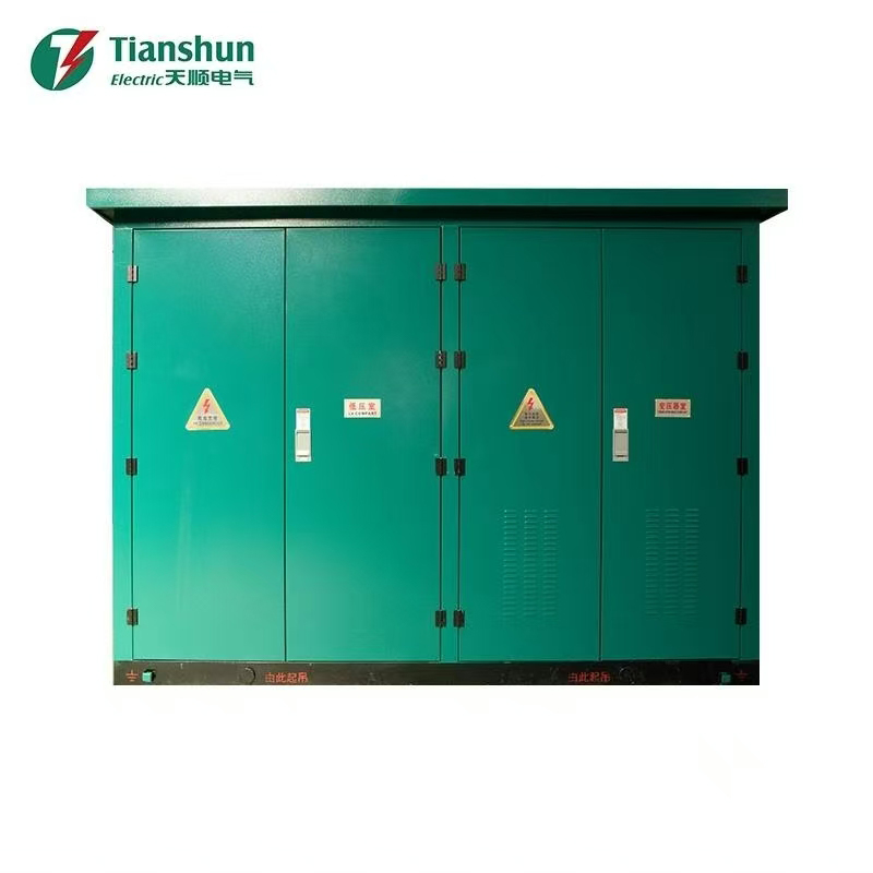
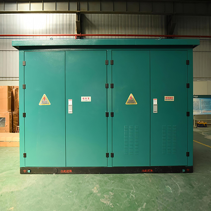
A prefabricated package substation can reduce site work when the bay arrangement is repeatable, but transport limits and foundation tolerances still control the schedule.
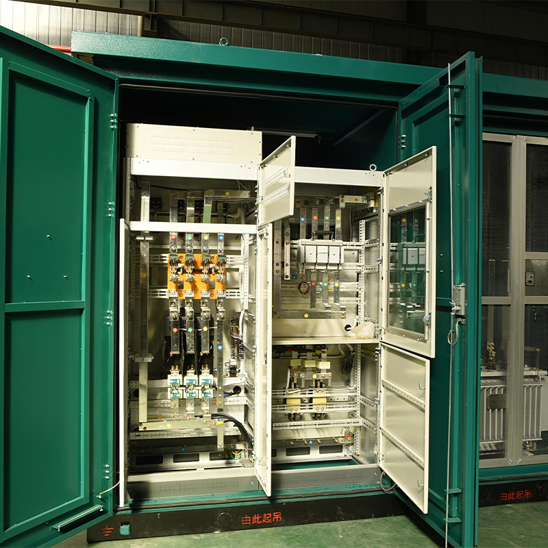 YB-12/0.4 Outdoor Prefabricated Package SubstationAssess repeatable bay arrangements, transport limits, foundation tolerances, and protection settings for a factory-assembled 12 kV/0.4 kV package substation.View Product →
- Lock the bay arrangement and single-line diagram before civil design.
- Confirm cable entry, trench routing, and termination space.
- Coordinate the earthing grid with equipment terminals and fences.
- Define fire walls, access roads, and lifting zones.
- Reserve future bays without blocking maintenance access.
Protection, Control, and Auxiliary Power
Protection settings must follow system studies, not catalogue defaults. CT ratio, VT burden, relay curve, trip circuit supervision, and DC autonomy decide whether a fault is cleared selectively. SCADA points should be agreed before factory acceptance testing, because late changes in alarms or interlocking are expensive.
- Fault studies and relay coordination completed before panel wiring
- CT and VT accuracy class matched to metering and protection
- DC battery autonomy calculated for trip and communication loads
- Interlocking logic tested against normal and emergency switching
- SCADA, alarm, and event lists signed off before FAT
Transformer Selection and Loss Evaluation
Transformer selection starts with voltage ratio, vector group, impedance, tap range, cooling, and noise. For indoor rooms, dry-type units reduce fire risk and simplify containment. Lifecycle cost should include no-load and load losses over the expected load profile, not only the purchase price.
 SCB13/SCB14 10 kV Dry-Type Distribution TransformersCompare enclosure rating, temperature rise, IP protection, ventilation, and lifecycle losses for indoor 630–2000 kVA cast-resin transformers.View Product →
Confirm enclosure rating, temperature rise, IP protection, and ventilation before comparing quotations. A transformer that fits the electrical room but cannot dissipate heat will limit the whole substation.
Commissioning and Acceptance Checks
A substation is ready when test records, interlocks, and operating procedures agree. The acceptance plan should link each test to a hold point and a signed record.
- Visual inspection, torque checks, and cleanliness before energisation
- Insulation resistance, polarity, and ratio tests on CTs and VTs
- Primary injection and secondary injection for protection relays
- Interlock, trip, and alarm tests using the approved switching schedule
- Power frequency withstand and partial discharge tests where specified
- SF6 gas density and dew point records for GIS equipment
- Transformer winding resistance, ratio, and earthing continuity
- SCADA point to point verification and event recording
Record actual values against manufacturer limits, not just pass or fail. Trend data helps later maintenance and fault investigation.
A Practical Procurement Checklist
Procurement works best when the technical package is complete. Include the single-line diagram, fault level, protection study, layout, interface matrix, spare parts list, test plan, and documentation schedule. Ask for factory acceptance test witnesses and site support terms in the same comparison.
- Rated voltage, current, frequency, and short-circuit rating
- Ambient temperature, altitude, humidity, and pollution level
- Interface schedule for cables, relays, SCADA, and civil works
- Factory test plan, inspection hold points, and witness scope
- Spare parts, special tools, and maintenance training
- Delivery milestones, packing, transport, and site support
Share the single-line diagram and site constraints with the supplier early through the contact page. A high-voltage electrical substation is a long-life asset, and the best quotation is the one that closes technical interfaces before the first bay is shipped.