

 English
 中文简体
 Español
 عربى

Point-on-Wave Switching Circuit Breaker: How Controlled Switching Works
Admin 2026-10-23Content
- 1 What Is Point-on-Wave Switching?
- 2 Why Circuit-Breaker Timing Matters
- 3 Where Point-on-Wave Switching Is Used
- 4 What Is Required for Reliable Point-on-Wave Operation
- 5 Practical Steps to Implement Point-on-Wave Switching
- 6 Limitations and Procurement Considerations
- 7 Controlled Switching in Modern Switchgear Design
- 8 Bottom Line
Closing a circuit breaker a few milliseconds too early or too late can turn a routine switching operation into a serious electrical disturbance. Energize a transformer at the wrong part of the AC cycle and the magnetizing inrush current can trip protection, distort voltage for nearby loads, or stress the insulation. A point-on-wave switching circuit breaker addresses this risk by timing the breaker contacts to a precise point on the voltage or current waveform.
In short, the breaker is not just fast; it is intentionally synchronized. This is what makes point-on-wave circuit breaker switching a practical reliability tool in low-voltage and high-voltage distribution systems.
What Is Point-on-Wave Switching?
Point-on-wave switching, also called controlled switching or synchronous switching, is the technique of operating a circuit breaker so that each phase opens or closes at a chosen electrical instant. The controller monitors the system voltage, identifies the phase angle, and issues a command early enough to compensate for the breaker's mechanical travel time.
For example, when a transformer is energized, the best closing point for the contact is usually near voltage peak. When a capacitor bank is energized, the preferred point is near voltage zero. Achieving those targets requires microsecond-level accuracy because the waveform angle changes rapidly.
| Application | Preferred instant | Main transient reduced |
|---|---|---|
| Transformer energization | Voltage peak | Magnetizing inrush current |
| Capacitor bank energization | Voltage zero | High-frequency inrush and overvoltage |
| Shunt reactor switching | Current zero | Chopping overvoltage and restrikes |
| Line or cable energization | Depends on network design | Switching overvoltage |
This is not a substitute for correct protection settings. It is an additional control layer that reduces the electrical and mechanical disturbance created by switching itself.
Why Circuit-Breaker Timing Matters
Switching timing matters because every arc interruption and every contact closure transfers energy at a specific point on the waveform. The same breaker can switch cleanly or create a damaging transient depending on when the contacts move.
- Transformer inrush. Closing too close to voltage zero can saturate the transformer core and produce high magnetizing inrush current. Controlled closing near voltage peak reduces that inrush.
- Restrikes. If a breaker interrupts at the wrong point, the arc may reignite, creating high-frequency overvoltages and repeated stress on the breaker and connected equipment.
- Capacitor transients. Closing a capacitor bank away from voltage zero produces a high-frequency inrush that can damage contacts and disturb power quality.
- Mechanical wear. High transients accelerate insulation ageing and increase maintenance frequency. A clean switching waveform helps the breaker and the switchgear last longer.
The practical effect is measurable: fewer unplanned trips, lower repair costs, better power quality, and longer equipment life.
Where Point-on-Wave Switching Is Used
The technology is most valuable where a single operation can disturb a sensitive network or damage a costly asset.
- Transformer switching in utility substations and large industrial plants, especially when transformer inrush causes voltage sag.
- Capacitor bank switching for reactive power compensation, where inrush can produce overvoltages.
- Shunt reactor switching on long transmission lines, where current chopping and restrikes are a real concern.
- Mining and process industries that cannot tolerate production stops caused by voltage dips.
- Renewable energy plants where transformers and medium-voltage collection networks are connected frequently.
What Is Required for Reliable Point-on-Wave Operation
Point-on-wave switching only works if the circuit breaker is mechanically predictable. The controller issues the command, but the breaker must close or open within a repeatable operating time.
- Stable operating time. The breaker should have low scatter between operations. A total scatter of less than 1 ms is often used as a practical starting point, depending on the application and controller specification.
- Reliable waveform reference. The controller needs accurate voltage transformer signals to detect zero crossings and phase angle. It also needs a stable internal time base to compensate for the next cycle.
- Per-phase control. In three-phase systems, each phase may need its own target because mechanical and electrical conditions are not identical.
- Commissioning measurement. Operating times must be measured on site, then entered or verified in the controller before normal service.
Type-tested operating-time data, such as the timing tests performed for IEC 62271-100, are the correct starting point for the control settings.
Practical Steps to Implement Point-on-Wave Switching
Implementation is more than entering a target angle in a menu. It is an engineering process that combines project data, breaker data, and field measurements.
- Identify the critical switching operation that causes the highest transient risk.
- Measure the breaker closing and opening times at the expected operating temperature.
- Simulate or calculate the target electrical instants for voltage peak, voltage zero, or current zero.
- Configure the controller with operating-time compensation curves for different control voltages and temperatures.
- Run actual switching tests and record voltage, current, and contact timing traces.
- Revise settings if inrush, restrikes, or overvoltage remain visible.
There is no universal setting for all breakers. The transformer size, capacitor bank rating, cable length, and breaker condition all affect the optimum point-on-wave target.
Limitations and Procurement Considerations
Point-on-wave switching is not a replacement for good protection or routine maintenance. It can only reduce transients if the breaker can move consistently and if the voltage signal is clean.
- Mechanical scatter. If the breaker operating time drifts with temperature, control voltage, or wear, the contact may miss the intended target.
- Contact wear. As contacts erode, the operating time changes. The controller must be updated with recent measurements.
- Retrofit complexity. Adding controlled switching to an old breaker may require a new mechanism, additional sensors, and more precise interlocks.
- Factory acceptance. A buyer should ask how the manufacturer measures operating time scatter and whether the settings can be proven with factory switchgear tests.
From a procurement perspective, the details matter more than the controller model. Ask about the controller's voltage input range, the circuit breaker's phase independence, and the commissioning procedure. These factors decide whether the installed scheme will operate as intended.
Controlled Switching in Modern Switchgear Design
Point-on-wave switching is not a separate box that can be added to any breaker. It has to be integrated into the protection and control architecture of the switchgear. For a 12 kV indoor distribution network, a metal-enclosed switchgear such as the KYN28A-12 is a straightforward platform because its operating mechanism and phase arrangement are stable and well understood.
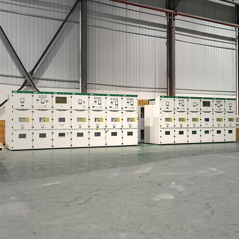 KYN28A-12 High-Voltage (HV) SwitchgearThe KYN28A-12 is a 12kV indoor armored withdrawable type AC metal-clad switchgear, which is a mainstream, mature, and universal high-voltage switchgear for domestic me...View Product →
When space is tight and reliability is critical, gas-insulated switchgear provides a compact enclosure with controlled mechanical tolerances. The stable environment inside a GIS is one of the reasons it is well suited for point-on-wave applications in industrial plants and utility networks.
 Gas Insulated Switchgear (GIS)The XGNT9-12 is a 12kV indoor box-type fixed AC metal-enclosed switchgear. It belongs to the next generation of miniaturized, integrated air-insulated switchgear, desi...View Product →
For transformer-related projects, controlled switching reduces stress on the transformer and on the balance of the distribution system. When oil containment is a concern, a dry-type transformer gives engineers an additional safety margin in building or industrial installations.
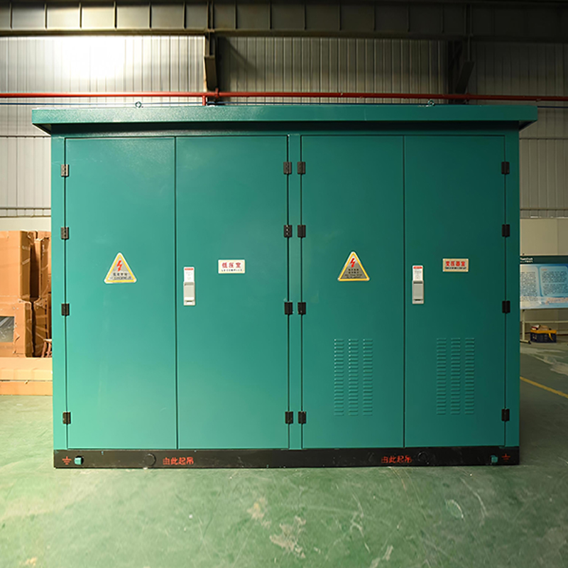 Dry-type TransformerThe SCB13-630~2000/10 and SCB14-630~2000/10 are 10kV three-phase epoxy resin cast dry-type transformers, with capacities ranging from 630kVA to 2000kVA. These transfor...View Product →
Bottom Line
A point-on-wave switching circuit breaker changes a random operation into a controlled operation. It limits transformer inrush, reduces restrikes, protects capacitor banks and reactors, and lowers stress on the whole switchgear assembly.
This is why, in our own switchgear work, we treat point-on-wave switching as part of project engineering. If you are planning a new feeder or upgrading an existing breaker bay, start from the switching target and work backward to the equipment. A discussion with the manufacturer early in the project is usually more effective than a later retrofit.
For exclusive deals and latest offers, sign up by entering your email address below.

-
Please feel free to contact us if needed!
Contact Us -
Quick Links
Home About Us Products Applications News Contact -
Contact Us
nbtsdq@163.com +86-15757467313 +86-574-65800646 No. 1, Jiuzhou Road, Xiangshan County, Ningbo City, Zhejiang Province, China -
Get Touch
