

 English
 中文简体
 Español
 عربى

How Substation High Voltage Design, Switchgear, and Procurement Fit Together
Admin 2026-10-02Content
A 35 kV feeder stops at the fence of an industrial park. The utility needs a switching point it can operate safely. The plant needs 400 V at the end of a production line. Everything between those two points is the high voltage substation, and most of the decisions made about it will still be in service twenty or thirty years from now.
The practical conclusion first: the voltage class decides the switchgear family, the switchgear family decides the building dimensions, and the building dimensions decide the project schedule. Settle those three in that order and procurement becomes a routine exercise. Settle them out of order and the room is built too small, the cable trenches sit in the wrong place, and the switchgear arrives after the civil work is sealed.
This guide covers what a high voltage substation does, which equipment blocks sit inside it, how voltage class drives equipment selection, and which details are worth checking before an order is placed.
What a High Voltage Substation Does
A substation is a node where several functions meet. It changes voltage, switches circuits in and out of service, protects the network from faults, and provides a point for metering and control. Not every installation performs all four tasks. A switching station mainly routes power, a step-down substation transforms and routes, and a distribution substation does both before sending feeders out to load centres.
The label high voltage is not a single number. Engineers work in bands, and the band determines which standards apply and how much space the installation needs.
| Voltage class | Typical role | Common equipment form |
|---|---|---|
| 12 kV | In-plant distribution, secondary side of a step-down, feeder switching | Metal-clad withdrawable or fixed indoor switchgear |
| 40.5 kV | Sub-transmission into large industrial sites and utility distribution nodes | Withdrawable indoor switchgear with wider phase spacing |
| 110 kV and above | Transmission entry and bulk transformation between grid levels | Outdoor air-insulated or gas-insulated switchgear in a yard layout |
Two consequences follow. Moving up one band does not mean buying the same cabinet with a larger number on the door; it means longer insulation distances, different test regimes and usually a different room. And the transformer ratio fixes the low side voltage, which in turn fixes the low voltage distribution equipment downstream.
The Functional Blocks Inside the Substation
Whatever the voltage, a substation is assembled from the same functional blocks. Reading a single-line diagram is mostly a matter of recognising them in sequence.
- Incoming line bay: the connection from the line, with surge arresters and a means of isolation.
- Busbars: the common node that ties bays together, arranged as single, double or sectionalised.
- Circuit breakers: the devices that interrupt fault current, rated above the prospective short-circuit level.
- Disconnectors: no-load isolation for maintenance with verifiable contact separation.
- Instrument transformers: current and voltage transformers that scale signals down for protection and metering.
- Protection and control: relays, trip circuits, the DC supply and the communication link to a supervisory system.
- Power transformers: the units that actually change voltage, oil-filled or dry type.
- Earthing system: the buried grid and bonding network that limits touch and step voltages during a fault.
Each block carries a scheduling consequence. Busbar arrangement decides maintenance rules for decades, protection philosophy decides how many cables run to the control room, and earthing design decides how much copper goes into the ground before the steel structure is erected.
How Voltage Class and Duty Drive Switchgear Selection
The switchgear is where most of the project budget and most of the interface risk sits. Three questions narrow the field quickly: what the system voltage is, what the short-circuit level is, and how often the breaker will be operated.
12 kV indoor distribution
At 12 kV, metal-clad withdrawable switchgear is the default for installations where a fault on one feeder should not disturb the rest of the board. The withdrawable truck lets maintenance crews replace a breaker without exposing the busbar, which matters in plants running continuous shifts. Fixed-pattern designs remain useful where switching frequency is low and the budget is tight, but they trade accessibility for cost.
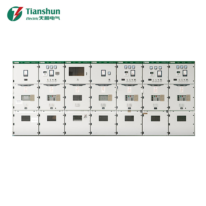
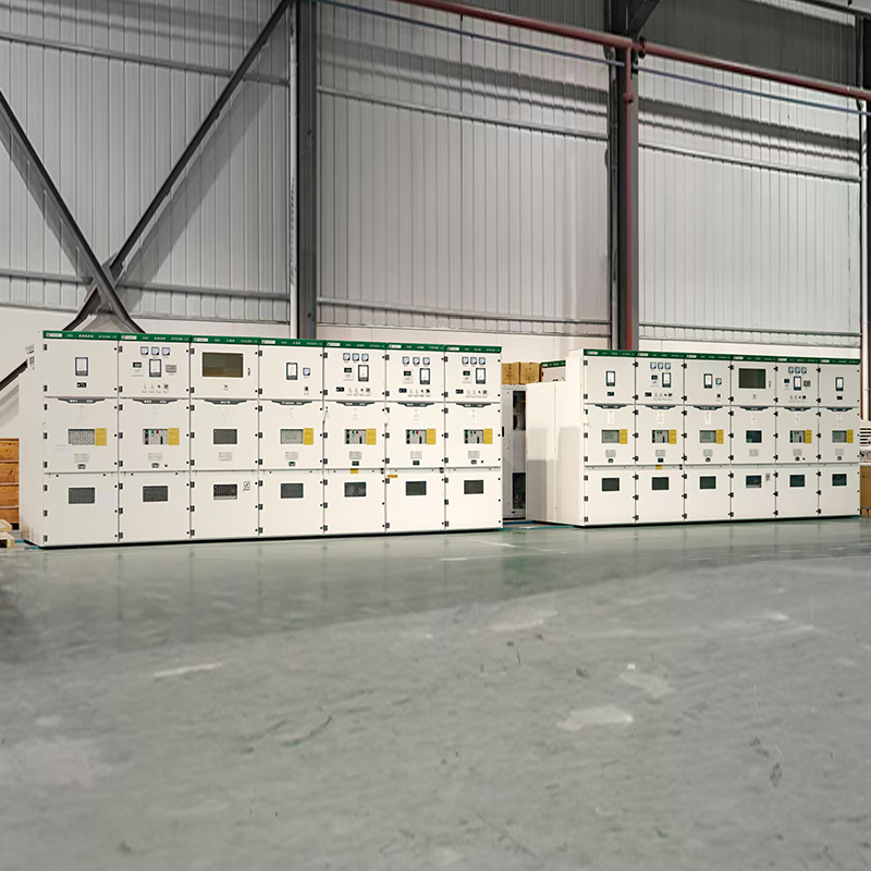 KYN28A-12 High-Voltage (HV) SwitchgearThe KYN28A-12 is a 12kV indoor armored withdrawable type AC metal-clad switchgear, which is a mainstream, mature, and universal high-voltage switchgear for domestic me...View Product →
40.5 kV sub-transmission
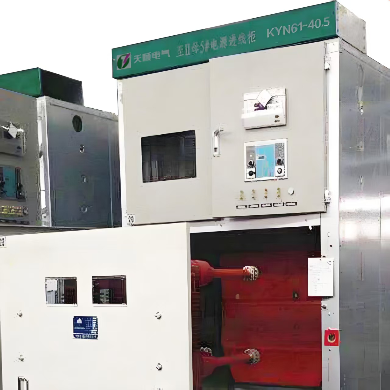
Moving to 40.5 kV changes the physical envelope more than the operating logic. Phase spacing grows, the breaker becomes heavier, and the handling equipment on site has to match. A board at this level is usually specified with a higher short-circuit withstand because it sits closer to the source.
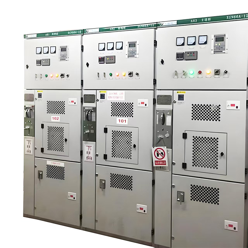
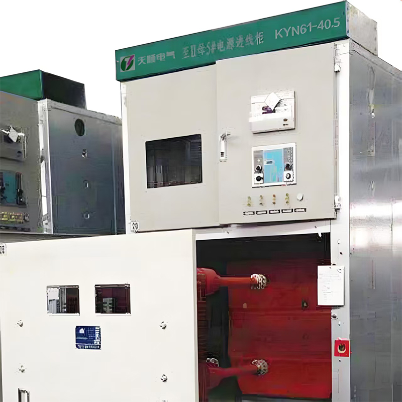 KYN61-40.5 High-Voltage (HV) SwitchgearThe KYN61-40.5 is a 40.5kV indoor armored withdrawable type AC metal-clad switchgear, which is the mainstream, standardized high-voltage distribution equipment for the...View Product →
Space-constrained and coastal locations
Where the room is small, the air is salty or humid, or the site sits in a coastal industrial area, gas-insulated switchgear changes the calculation. Sealed enclosures remove most of the airborne contamination problem and shrink the footprint, at the cost of more specialised service requirements.
Whichever family is chosen, the specification should name the standards the equipment is tested to, the ambient temperature the ratings assume, and the installation altitude. A board rated at 40 degrees Celsius ambient loses capacity in an unventilated room, and equipment rated for 1000 metres of altitude needs derating above that point.
Clearances, Earthing and Safety Design
Layout work is where the substation stops being a catalogue exercise. The numbers that drive it are not negotiable, and they are far easier to accommodate at the drawing stage than after the walls are up.
- Insulation distances: phase-to-phase and phase-to-earth clearances grow with voltage, so 12 kV equipment fits a compact room while 40.5 kV does not.
- Working space: withdrawable breakers need a corridor in front of the board long enough for the truck to be pulled out and inspected.
- Cable and busbar routes: incoming cables, busbar ducts and control cabling each need separate paths with defined bending radii.
- Earthing performance: grid resistance targets are commonly specified at around 1 ohm for high voltage installations, with calculated touch and step voltages rather than a resistance value alone.
- Ventilation and fire: transformer rooms, cable basements and battery rooms each carry different ventilation and detection requirements.
- Environmental protection: outdoor enclosures are usually specified at IP54 or higher, with anti-condensation heating where temperature swings cause internal moisture.
The practical test of a layout is maintenance. If a crew cannot isolate one feeder, earth it and work on it without shutting down the rest of the board, the design will be worked around informally for years, which is a worse outcome than a slightly larger room.
Procurement Checks That Prevent Later Rework
Most substation delays do not come from equipment failure. They come from mismatches discovered at site: a relay that will not talk to the plant network, a busbar rating quoted at a different ambient, a drawing set that does not match the delivered panel.
| Item to verify | Detail to confirm | Consequence if missed |
|---|---|---|
| Type and routine test reports | Which standard applies, and which tests were performed on the actual units | Equipment may be rejected by the utility or the insurer |
| Rated current at site ambient | Whether the rating is quoted at 40 degrees Celsius or at a lower reference | Derating, higher temperature rise and shortened insulation life |
| Short-circuit withstand | Whether it exceeds the prospective fault level at the point of connection | Breaker or busbar damage during the first fault |
| Protection protocol | IEC 61850, Modbus or hard-wired, and who configures the settings | Extra gateway hardware and longer commissioning |
| Interlocks and key scheme | Whether mechanical and electrical interlocks sit inside the base price | Unsafe operating sequences or field modifications |
| Delivery split and storage | Which items arrive first, and how they are stored before energisation | Moisture ingress and insulation problems before handover |
Documentation deserves equal attention. If as-built drawings, test certificates and relay configuration files arrive only on paper or only in a language the operations team does not read daily, that team starts its working life with a handicap.
Packaged Substations and Site Delivery
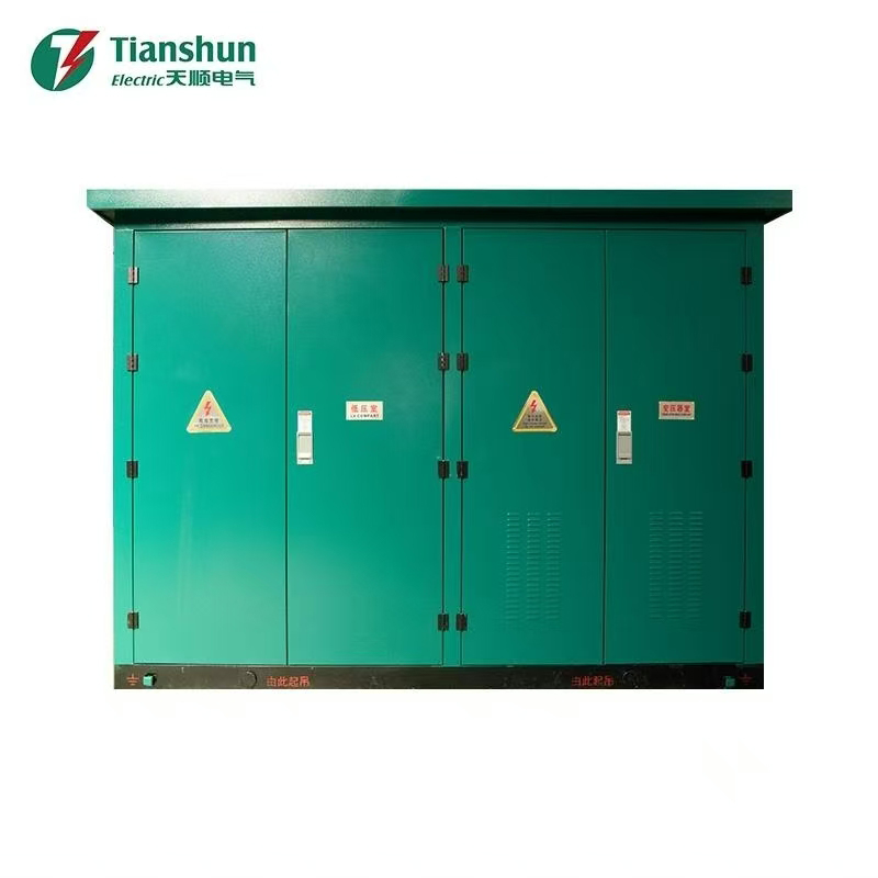
Where the load is dispersed, a prefabricated box-type substation often beats a conventional building. The transformer, high voltage incoming, low voltage outgoing and auxiliary circuits arrive as one assembly that was tested before shipment. Site work reduces to a foundation, cable connections and commissioning, which shortens the schedule and moves labour cost out of the field.
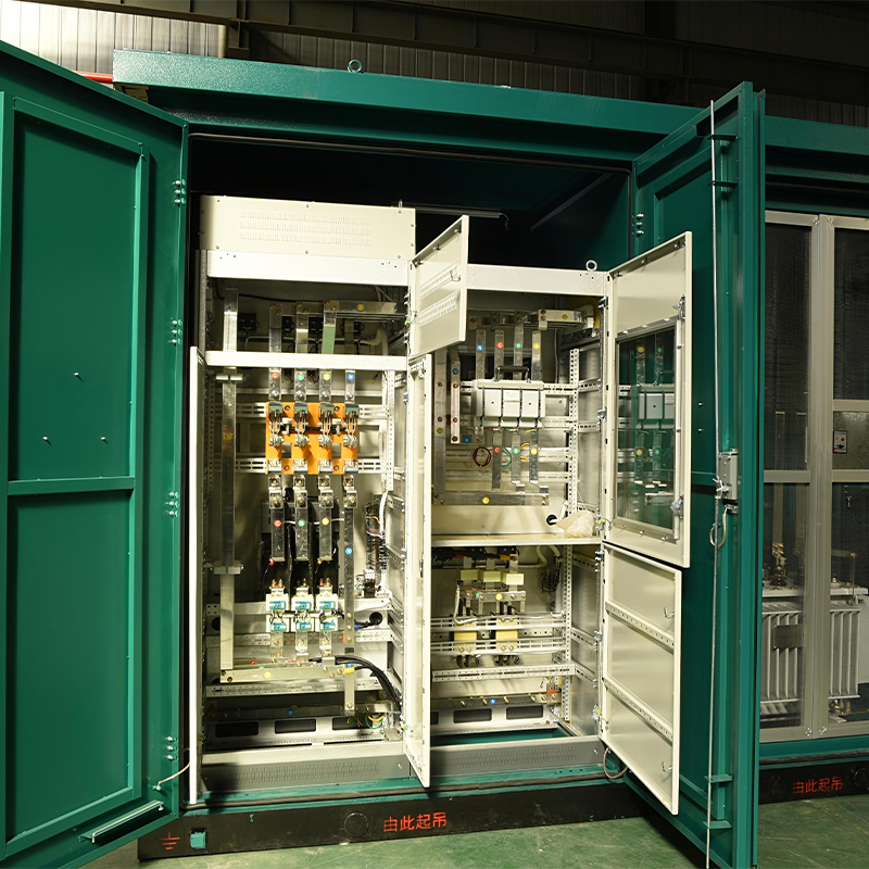 Package SubstationThe YB-12/0.4 is a 12kV/0.4kV outdoor prefabricated package substation (box substation). It integrates high-voltage distribution, transformers, and low-voltage distrib...View Product →
The trade-off is planning discipline. The enclosure footprint, cable entry positions and ventilation openings are fixed at the factory, so the civil design has to be finalised early. It also pays to confirm how the transformer is protected, how the unit is earthed on site, and who owns the interface between the packaged unit and the plant distribution network.
For readers still comparing topologies, our overview of high voltage distribution systems explains how the substation fits into the wider arrangement from source to load. Once the voltage class, the switchgear family and the room dimensions are agreed, the remaining conversation is commercial, and that is the right moment to talk through the project with the people who will build it.
Getting the Sequence Right
Substation projects reward order. The sequence that produces the fewest surprises is short.
- Confirm the system voltage and the prospective short-circuit level at the point of connection.
- Choose the busbar arrangement based on how the plant intends to maintain the installation.
- Select the switchgear family, then fix the room dimensions around it.
- Design the earthing grid and cable routes before structural steel goes up.
- Verify ratings against site ambient, altitude and enclosure class rather than catalogue headlines.
- Agree the protection protocol, documentation language and delivery schedule inside the purchase order.
Get those six steps right and the high voltage substation becomes what it should be: a quiet, predictable piece of infrastructure that converts voltage, isolates faults and stays out of the way of production for the next thirty years.
For exclusive deals and latest offers, sign up by entering your email address below.

-
Please feel free to contact us if needed!
Contact Us -
Quick Links
Home About Us Products Applications News Contact -
Contact Us
nbtsdq@163.com +86-15757467313 +86-574-65800646 No. 1, Jiuzhou Road, Xiangshan County, Ningbo City, Zhejiang Province, China -
Get Touch
