

 English
 中文简体
 Español
 عربى

Point on Wave Controller: Working Principle, Benefits, and Selection Guide
Admin 2026-09-25Content
Energizing a 10 MVA transformer is not supposed to be dramatic. In an uncontrolled medium-voltage switchboard, however, it often is: the breaker closes at a random instant on the 50 Hz or 60 Hz waveform, the core saturates, and an inrush current of six to ten times the transformer rating flows for several cycles. The bus voltage dips, the differential protection may operate falsely, and the breaker contacts erode a little more each time. Capacitor bank switching follows the same pattern; close at the wrong point and the bank sees a current spike of tens of kiloamperes. A point on wave controller fixes the root cause by placing the switching instant exactly where the system can tolerate it.
01What Is a Point on Wave Controller?
A point on wave (PoW) controller, also called a controlled switching device (CSD), is a microprocessor-based relay that times a circuit breaker's contact movement relative to the power system voltage and current waveforms.
Every breaker has a mechanical operating time: the interval between receiving a close command and the contacts actually touching. In a medium-voltage vacuum breaker this is on the order of 30 to 60 ms; in a high-voltage SF6 breaker it can exceed 100 ms. That interval changes with ambient temperature, mechanism lubrication, auxiliary voltage, and contact wear. One millisecond at 50 Hz is roughly 18 degrees of the waveform, at 60 Hz about 21.6 degrees, so even a small drift moves the switching point well away from the intended angle.
The PoW controller solves this by measuring the system voltage and current in real time, storing the breaker's operating time statistics in memory, and sending the close or open command early so the contacts make or break at the intended angle. Adaptive firmware recalculates the timing after every operation, so the controller gradually tracks the mechanism as it ages.
02How a Point on Wave Controller Works
The target instant depends on the load being switched. The first line of defence is a simple operating rule: close into capacitive loads at voltage zero, close into inductive loads at voltage peak, and time breaker opening to avoid restrikes and current chopping.
| Equipment | Preferred closing point | Transient avoided |
|---|---|---|
| Power transformer | Voltage peak, compensated for residual flux | Core saturation and magnetizing inrush |
| Capacitor bank | Voltage zero crossing | Capacitor inrush and bus voltage dip |
| Shunt reactor | Voltage peak | DC flux offset and switching overvoltage |
Transformer energization is the demanding case. If the core still contains residual flux from the previous de-energization, the controller must know, estimate, or even force that flux so the prospective flux at contact touch matches the residual value. Modern controllers therefore also perform a controlled opening, recording the flux state at breaker interruption so the next closing angle is true. Ignoring residual flux is the most common reason an otherwise well-engineered PoW installation underperforms.
03Why Controlled Switching Matters
Measured against the cost of damage, controlled switching is a small investment that changes how every subsequent switching event behaves.
- Transformer inrush: uncontrolled inrush of 6 to 10 times rated current falls to less than 1.5 times rated current, and in many cases to the transformer's normal magnetizing level. Winding stress, acoustic noise, and false differential relay operations are all reduced.
- Capacitor bank protection: inrush current drops from tens of kiloamperes to the steady-state bank current, and the high-frequency transients that stress capacitor elements disappear.
- Bus voltage stability: voltage dips associated with transformer and reactor energization are reduced to a few percent, protecting sensitive loads on the same bus.
- Breaker duty: fewer restrikes and less arcing extend contact life. This is especially important in gas-insulated switchgear, where internal inspection is costly.
- Power quality: switching operations no longer generate voltage notches or nuisance trips in downstream drives, programmable controllers, and electronic meters.
The asset that benefits most is the transformer. Every uncontrolled inrush applies a mechanical impulse to the windings; accumulated over years, it contributes to winding movement, loose clamping, and eventual partial discharge. For distribution transformers that are energized every day in factories, wind and solar plants, and mine sites, eliminating the uncontrolled inrush on a daily basis is inexpensive insurance.
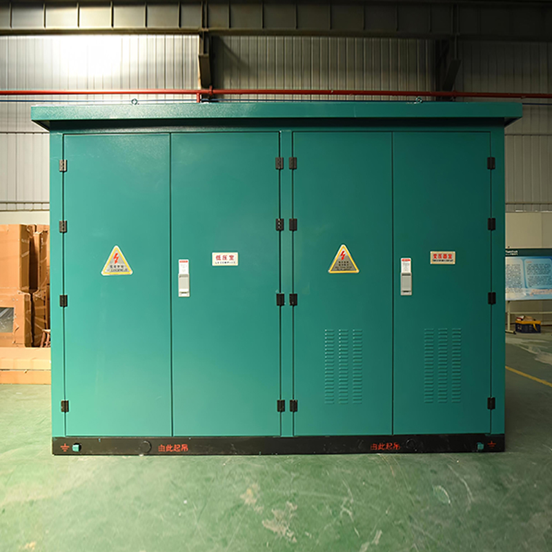 SCB13/SCB14 Epoxy Resin Cast Dry-Type Transformer for DistributionFor distribution transformers energized daily in factories and plants, controlled switching prevents winding stress from inrush currents. This dry-type model offers fire safety and efficiency for indoor and renewable applications.View Product →
04Where Point on Wave Control Belongs
Controlled switching earns its keep in medium- and high-voltage networks from about 6 kV upward, wherever a breaker routinely switches a magnetizing or reactive load. The dividing line between where these transients matter and where they can be ignored follows the same logic described in our backgrounder on the high-voltage distribution system.
Three installation types justify the cost without debate:
- Industrial plants that energize a main transformer once or twice every day at shift start.
- Reactive compensation schemes where a capacitor bank is switched by time clock or voltage control several times a day.
- Renewable generation sites where the step-up transformer is disconnected after every cloud or storm trip and reconnected when the resource returns.
Gas-insulated switchgear is a particularly strong candidate. The breaker contacts live inside a sealed SF6 chamber; each restrike decomposes a little gas and deposits carbon on arcing contacts. Inspection means opening the enclosure, which is a major outage. Point on wave control keeps the sealed chamber clean over the life of the asset and directly reduces the probability of an internal arc.
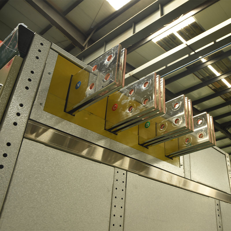 XGNT9-12 Gas Insulated Switchgear for Sealed Chamber ReliabilityIn GIS, each restrike degrades SF6 and deposits carbon on contacts. Point-on-wave control keeps the sealed chamber clean, reducing internal arc risk. This compact 12kV switchgear suits space-constrained urban and industrial networks.View Product →
05Selecting a Point on Wave Controller
If you are evaluating PoW controllers for a new or retrofitted switchboard, the specification must go beyond a relay model number. Five details decide whether the installation actually delivers the expected benefit.
- Breaker operating-time scatter. The controller is only as good as the breaker's repeatability. Ask the switchgear manufacturer for the minimum and maximum closing time at the declared control voltages and temperatures; total scatter should be well below 2 ms for a standard power-frequency application.
- Residual flux handling. For transformer switching, confirm that the controller estimates or controls residual flux. Otherwise the first closing after a de-energization can still show significant inrush.
- Independent pole control. Capacitor banks and ungrounded transformer connections may require independent timing for each pole, with targets spaced 120 degrees apart. A three-phase simultaneous controller is not always sufficient.
- Adaptive compensation. The controller should accept temperature and control-voltage inputs and revise its timing model after every close-open cycle.
- Integration and records. Look for a communication interface such as IEC 61850 or Modbus, plus event logs and waveforms. A PoW controller is also the best diagnostic instrument on the switchgear; choose one that can prove what happened during each operation.
On a practical level, specify the controller together with the switchgear. Metal-clad withdrawable apparatus such as the KYN28A-12 hosts a vacuum breaker with a compact and consistent operating mechanism, which makes it a natural platform for controlled closing. The switchgear supplier should provide the breaker timing data, a separate control compartment, and the interwiring the controller requires.
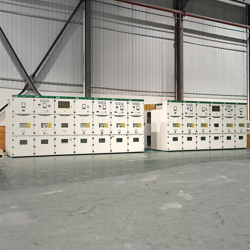 KYN28A-12 Armored Withdrawable Switchgear for Controlled SwitchingThis metal-clad switchgear hosts a vacuum breaker with consistent timing, ideal for point-on-wave control. Its withdrawable trolley and independent compartments simplify maintenance and enhance safety in medium-voltage distribution.View Product →
06Uncontrolled versus Controlled Closing in Numbers
The practical value is easiest to judge with the figures side by side.
| Parameter | Uncontrolled closing | With point on wave controller |
|---|---|---|
| Transformer inrush | 6 to 10 times rated current | Below 1.5 times rated current |
| Capacitor inrush | 10 to 30 kA peak | Near the steady-state bank current |
| Bus voltage dip | 10 to 20 percent for several cycles | 1 to 2 percent |
| Restrike probability (capacitor switching) | Depends on breaker age and point of close | Negligible when target and breaker are well characterized |
| Contact maintenance interval | Shortened by cumulative arcing | Extended |
The choice is not between adding a PoW controller and replacing a breaker. It is between controlling the switching instant and continuing to let a random phase angle decide. For plants that cycle large transformers or capacitor banks every day, the controller pays for itself within the first few avoided protection trips and the first inspection interval that is extended.
When you are ready to specify an arrangement for your system, contact our engineering team with the transformer and breaker nameplate data. The correct target angle for your equipment can be calculated before you order a single component.
For exclusive deals and latest offers, sign up by entering your email address below.

-
Please feel free to contact us if needed!
Contact Us -
Quick Links
Home About Us Products Applications News Contact -
Contact Us
nbtsdq@163.com +86-15757467313 +86-574-65800646 No. 1, Jiuzhou Road, Xiangshan County, Ningbo City, Zhejiang Province, China -
Get Touch
