

 English
 中文简体
 Español
 عربى

Point on Wave Controlled Switching of High Voltage Circuit Breakers Explained
Admin 2026-10-09Content
- 1 The Controller Decides in Electrical Degrees, Not Milliseconds
- 2 Target Electrical Angle Depends on What Is Being Switched
- 3 Mechanical Time Scatter Is the Real Limit
- 4 What the Breaker Must Provide for Controlled Switching
- 5 Procurement and Switchgear Integration Checklist
- 6 Commissioning and Operational Verification
A 10 kV substation energizes the same shunt capacitor bank twice a quarter. Every close operation produces an inrush current that peaks at six to eight times the steady state value, holds for several cycles, and drags the bus voltage down with it. The breaker is not faulty. The contacts are simply closing at an unfavourable electrical angle, and that is a problem with a known engineering fix.
The short answer: point on wave controlled switching, also called controlled or synchronous switching, issues each pole's close or open command at a defined point on the reference voltage waveform and offsets that command by the breaker's own mechanical operating time. The value does not come from the algorithm. It comes from how repeatable the mechanism is. If per pole operating time holds within roughly 1 ms across the year, inrush, overvoltages and contact wear all fall. If it does not, no controller specification compensates for it.
The Controller Decides in Electrical Degrees, Not Milliseconds
A point on wave controller continuously samples a reference voltage, usually a busbar VT and sometimes a line side VT. It derives the phase angle from that waveform and, when a target angle is approaching, issues the command ahead of time by the expected mechanical operating time of the breaker.
At 50 Hz one cycle lasts 20 ms and 1 ms equals 18 electrical degrees. At 60 Hz, 1 ms equals 21.6 degrees. That conversion sets the practical accuracy ceiling. A 10 degree error at the target point is only 0.56 ms at 50 Hz, which is smaller than the natural scatter of most mechanisms. This is why the switching study, rather than the controller datasheet, decides what accuracy is achievable, and why controlled switching is normally evaluated as part of the wider high voltage distribution system instead of being bought as a stand alone relay function.
Target Electrical Angle Depends on What Is Being Switched
There is no universal target point. The correct angle follows from the physics of the load and from what the switching operation is meant to suppress.
| Switched equipment | Typical closing target | Typical opening target | Main reason |
|---|---|---|---|
| Shunt capacitor bank | Voltage zero crossing, matched to residual charge | Current zero with a small margin | Suppress high frequency inrush and restrike |
| Power transformer | Near voltage peak, offset for residual flux | Current zero | Limit inrush current and flux excursion |
| Overhead line or cable | Near voltage zero crossing | Current zero | Reduce travelling wave overvoltage |
| Shunt reactor | Near voltage peak | Current zero with controlled margin | Avoid restrike and current chopping transients |
Treat the table as orientation only. The actual target angles come from a switching study that accounts for breaker scatter, residual charge, trapped flux and the insulation coordination margin. Copying a default value out of a controller manual without that study is a common and expensive mistake.
Transformer energization is the classic case. Residual flux stays in the core after opening, and the closing angle decides how far the flux swings in the first cycle. Closing near the voltage peak keeps the flux offset bounded. Closing at a zero crossing can drive the core into saturation and produce an inrush current that trips protection on an otherwise healthy transformer.
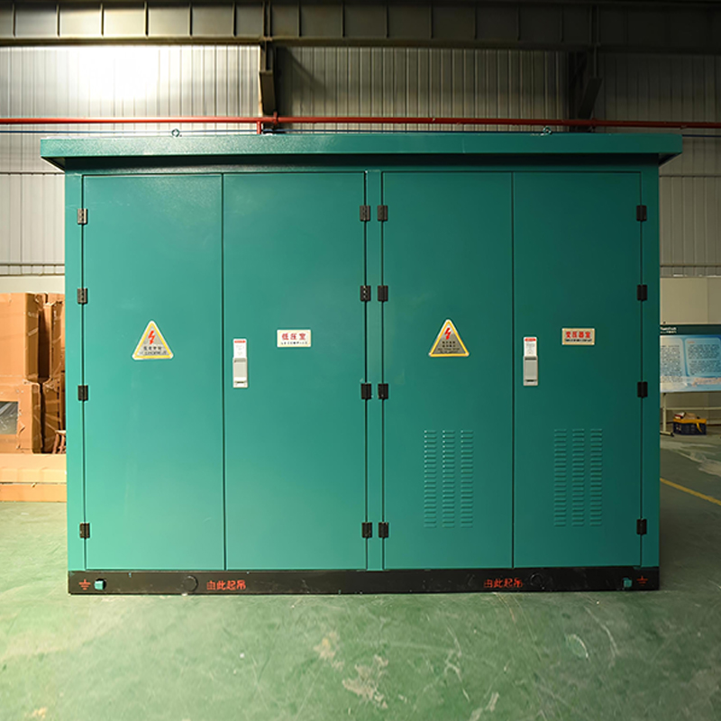 SCB13 and SCB14 10 kV Dry-Type TransformersEpoxy resin cast three-phase dry-type transformers from 630 to 2000 kVA for indoor distribution; consider inrush behavior because dry windings have shorter thermal time constants.View Product →
Dry type units behave the same way electrically, but the winding has a shorter thermal time constant, so repeated mis-energization accumulates degradation faster than it would in an oil filled unit.
Mechanical Time Scatter Is the Real Limit
Ambient temperature, control coil voltage, idle time and mechanism wear all move the closing and opening times. A breaker that opens in 28 ms at 20 degrees Celsius and 100 percent coil voltage may open in 34 ms at minus 10 degrees Celsius and 85 percent coil voltage. Six milliseconds is 108 electrical degrees at 50 Hz, more than enough to destroy any fixed target value.
A competent controller learns from every operation. It measures the actual contact operating time and corrects the next estimate, and some products add temperature and coil voltage compensation on top of that. The net effect is that the controller follows the breaker, not the other way round.
So the specification number that matters is not target angle resolution. It is per pole mechanical time consistency across the defined temperature and control voltage range, held over the maintenance interval. That number belongs in the breaker specification, stated in milliseconds, per pole.
What the Breaker Must Provide for Controlled Switching
Controlled switching is a specification decision taken at the switchgear level, so it belongs in the tendering documents for high voltage switchgear rather than in a later automation package. Four conditions have to be met before the controller has anything useful to work with.
- Independent pole operation, with a separate closing and opening coil for each pole.
- A reference voltage channel at the correct location, busbar side or line side, matching the switching duty.
- Repeatable per pole operating time that has been measured rather than assumed.
- A command path from controller to coil with low and stable transmission delay.
The first condition eliminates most candidate switchgear. A three phase gang operated breaker, where one mechanism drives all three poles, cannot be switched pole by pole no matter what the controller datasheet claims.
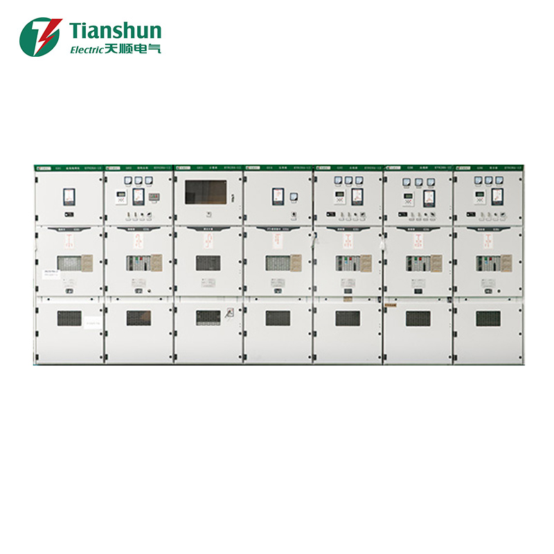
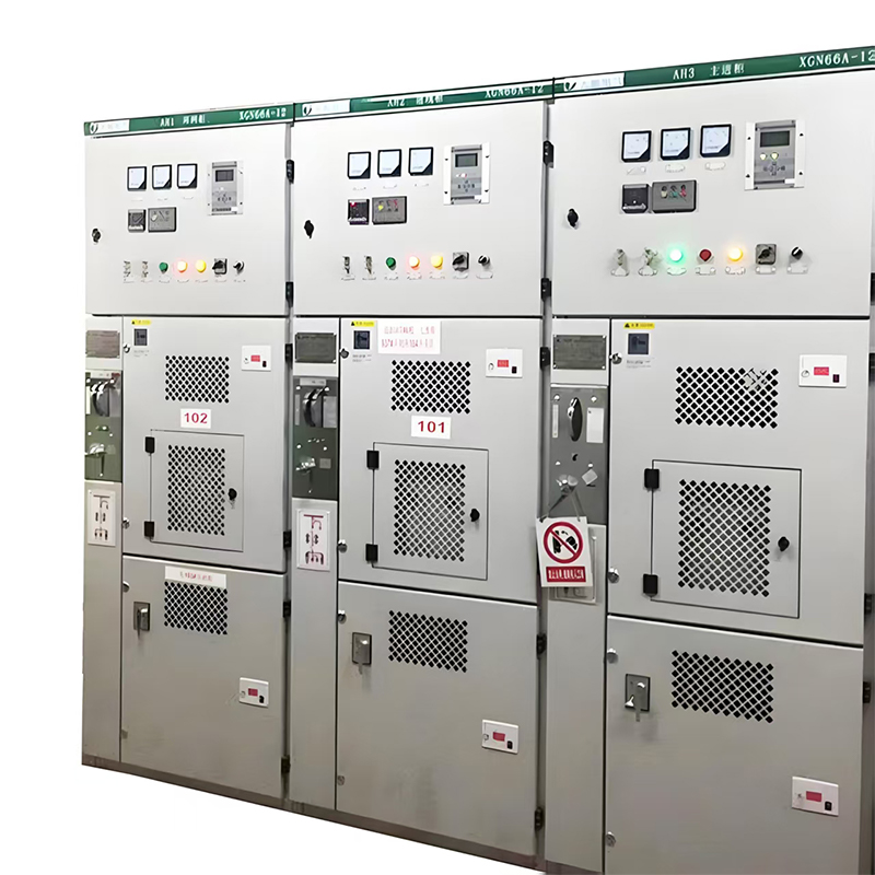
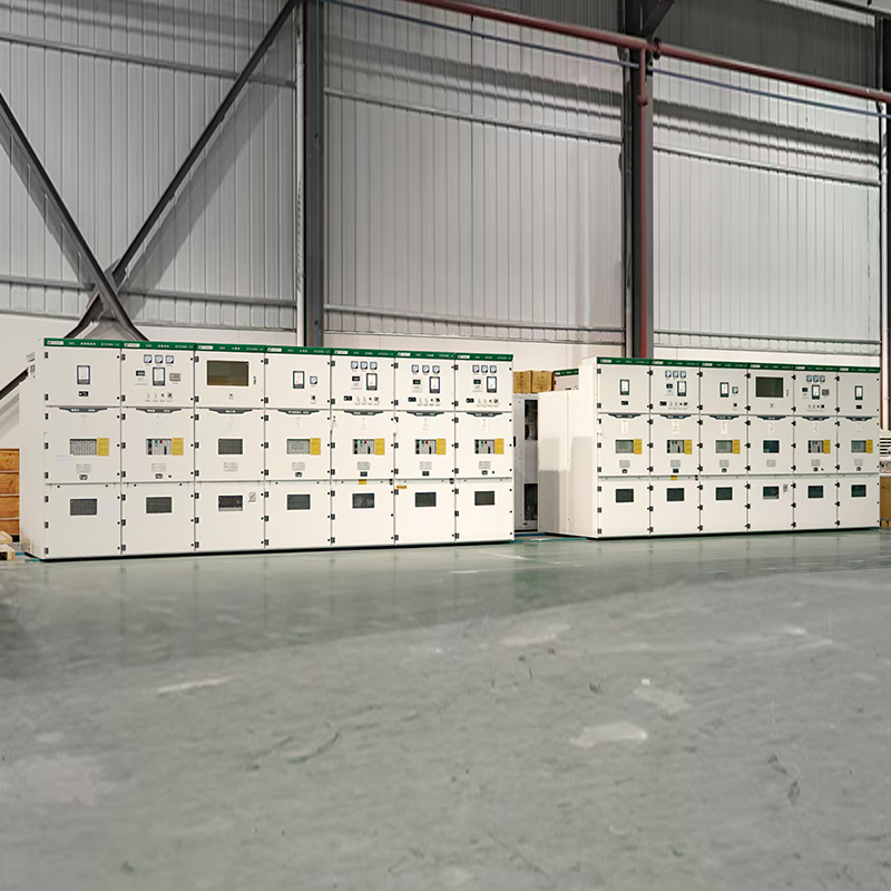 KYN28A-12 12 kV Indoor Metal-Clad Withdrawable Switchgear12 kV indoor armored withdrawable switchgear for medium-voltage distribution; its withdrawable breaker truck permits isolation without de-energizing the entire busbar.View Product →
In 12 kV distribution practice this usually points to a withdrawable metal clad unit with single pole operating mechanisms, specified that way from the start rather than retrofitted after delivery.
Procurement and Switchgear Integration Checklist
When a controlled switching scheme is specified, these are the items that decide whether it works in service rather than only on the test bench.
- Per pole operating time scatter, stated in milliseconds, across the full ambient temperature range.
- Per pole operating time scatter across the control voltage range, typically 85 to 110 percent of rated.
- Number and location of reference voltage channels required for each switching duty.
- Separate closing and opening target angles, since the two operations rarely share a value.
- Event records that store measured operating time and achieved angle for every pole, every operation.
- Communication to the substation control system, with time synchronisation adequate for event correlation.
For 40.5 kV installations the same logic applies at a higher insulation level, where the operating energy and the mechanical tolerances are both larger.
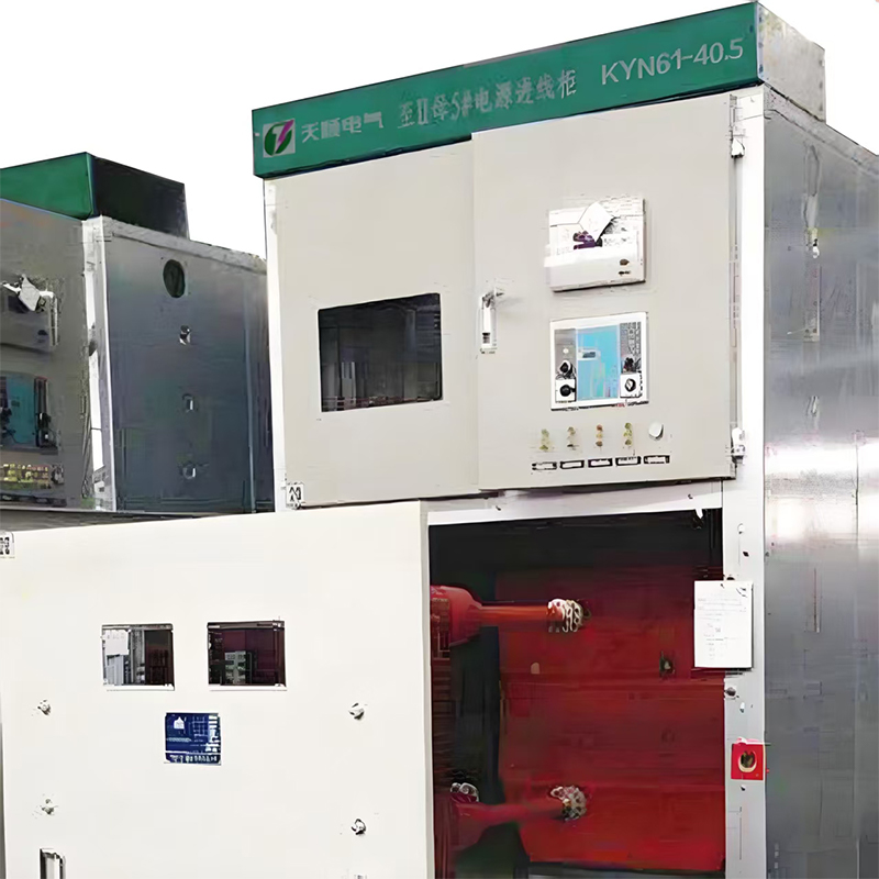 KYN61-40.5 40.5 kV Indoor Metal-Clad Withdrawable Switchgear40.5 kV indoor armored withdrawable switchgear for 35 kV distribution, with independent circuit breaker, busbar, cable, and relay compartments and mechanical interlocks.View Product →
At either voltage level, the controlled switching requirement should be written into the switchgear specification alongside the usual ratings. Retrofitting single pole mechanisms and separate coils after delivery is rarely economical.
Commissioning and Operational Verification
Controlled switching is not a set and forget setting. Commissioning should record per pole closing and opening times at 85, 100 and 110 percent control voltage, repeat the operations enough times to establish scatter, and compare the achieved angle against the commanded target.
Once in service, the controller should log measured operating time and angle error for every pole on every operation. Those records detect mechanism degradation before the inrush current reappears on the busbar. A controller that cannot produce them leaves no way to verify the scheme until something visible fails.
Point on wave controlled switching is ultimately a mechanical repeatability problem dressed up as a control problem. Choose the breaker first, insist on evidence of stable per pole operating times, and then design the controller logic around what the mechanism can actually deliver. Getting that order wrong produces a precise controller attached to a mechanism that cannot hold its own timing, and the inrush current returns exactly as it was before.
For exclusive deals and latest offers, sign up by entering your email address below.

-
Please feel free to contact us if needed!
Contact Us -
Quick Links
Home About Us Products Applications News Contact -
Contact Us
nbtsdq@163.com +86-15757467313 +86-574-65800646 No. 1, Jiuzhou Road, Xiangshan County, Ningbo City, Zhejiang Province, China -
Get Touch
